3D lighting monitoring method, 3D lighting monitoring device and 3D lighting monitoring system

A lighting system and 3D technology, applied in the field of intelligent buildings, can solve problems such as inability to accurately locate energy consumption, unreasonable management strategies, and insufficiently intuitive information display forms

Active Publication Date: 2015-07-08
BEIJING PERSAGY ENERGY SAVING TECH
View PDF5 Cites 7 Cited by
  • Summary
  • Abstract
  • Description
  • Claims
  • Application Information

AI Technical Summary

Problems solved by technology

[0003] The inventor found that the existing lighting system monitoring is limited to the information display in two-dimensional space, and the information display form is not intuitive enough. In addition, there are differences in energy consumption levels of different lighting equipment. It is difficult for managers to understand the operation of the entire lighting system from the above description. There is an overall grasp of the situation, resulting in the inability to accurately locate unreasonable energy use or deficiencies in management strategies

Method used


Image

  • 3D lighting monitoring method, 3D lighting monitoring device and 3D lighting monitoring system
  • 3D lighting monitoring method, 3D lighting monitoring device and 3D lighting monitoring system
  • 3D lighting monitoring method, 3D lighting monitoring device and 3D lighting monitoring system

Examples


Embodiment Construction

[0027] The present invention will be further described in detail below in conjunction with the accompanying drawings and embodiments. It should be understood that the specific embodiments described here are only used to explain the present invention, but not to limit the present invention. In addition, it should be noted that, for the convenience of description, only parts related to the present invention are shown in the drawings but not all content.

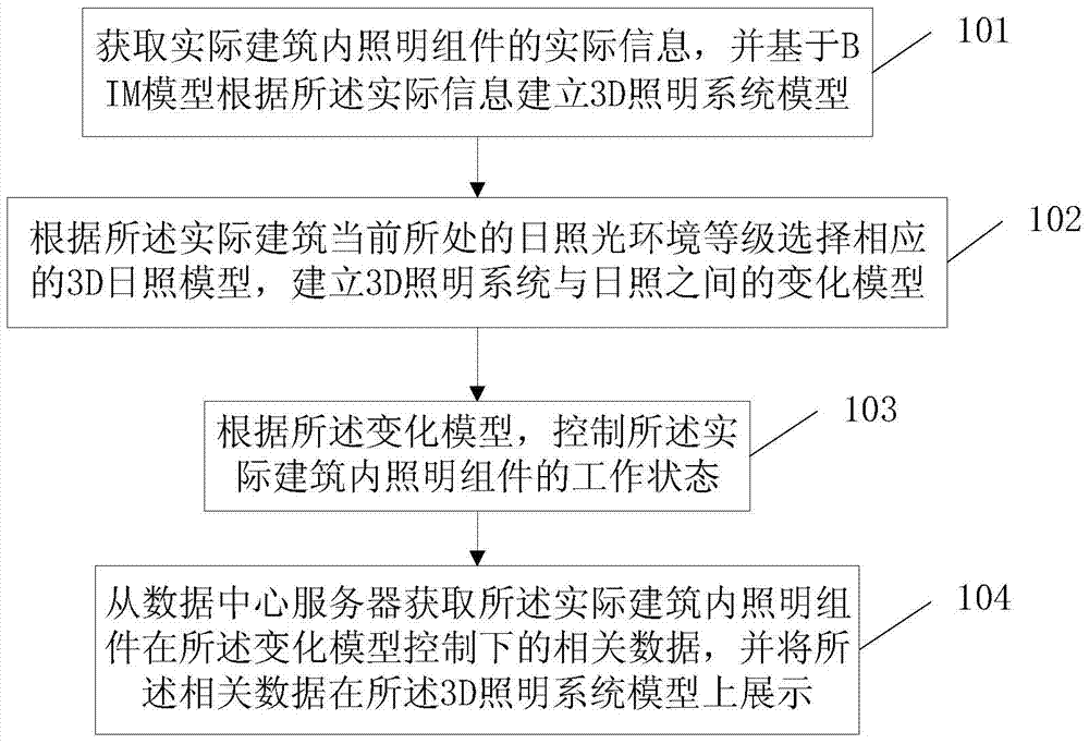
[0028] An embodiment of the present invention provides a 3D lighting monitoring method, such as figure 1 As shown, the method includes:

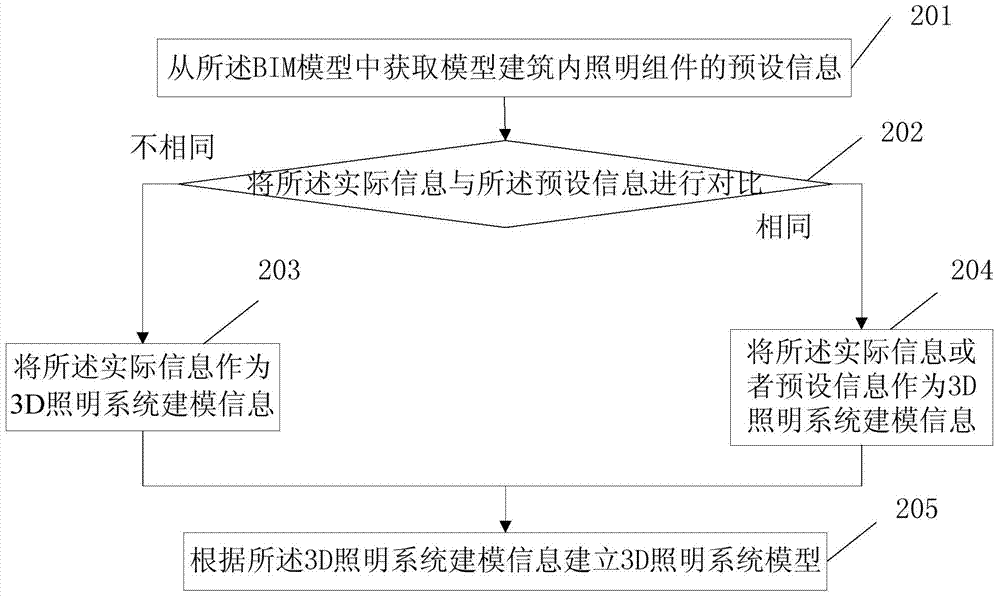
[0029] 101. Acquire actual information of lighting components in an actual building, and establish a 3D lighting system model based on the actual information based on a BIM model.

[0030] Wherein, the actual information may include but not limited to spatial relative position information and attribute information, wherein, spatial relative position information includes outdoor lighting, us...


PUM


Abstract

The invention discloses a 3D lighting monitoring method, a 3D lighting monitoring device and a 3D lighting monitoring system, and relates to the technical field of intelligent buildings. The operation state of lighting can be monitored, analyzed and managed more visually, comprehensively and completely. Moreover, lighting control can be realized by combining lighting operation state monitoring, analyzing and managing with a sunlight model, and energy saving can be achieved. The method of the invention mainly comprises the following steps: acquiring actual information of a lighting assembly in an actual building, and establishing a 3D lighting system model according to the actual information based on BIM (building information modeling); selecting a corresponding 3D sunlight model according to the level of a sunlight environment where the actual building is located currently, and establishing a change model between the 3D lighting system model and sunlight; controlling the working state of the lighting assembly in the actual building according to the change model; and acquiring related data of the lighting assembly in the actual building under the control of the change model from a data center server, and displaying the related data on the 3D lighting system model. The method of the invention is mainly used in the process of 3D lighting monitoring.

Description

technical field [0001] The invention relates to the technical field of intelligent buildings, in particular to the field of energy consumption monitoring in intelligent buildings, and in particular to a 3D lighting monitoring method, device and system. Background technique [0002] Green lighting and low-carbon lighting are important trends in the development of electrical lighting systems for intelligent buildings. Now the architectural lighting system does not simply pursue the saving of system power consumption, but through various optimization schemes on the basis of meeting the basic lighting functional characteristics of the building, so that the technical indicators of the entire lighting system such as illuminance and brightness can meet the functional requirements of the relevant lighting area. , to provide people with a high-quality and efficient lighting environment. In order to facilitate centralized understanding of the operating status of the lighting system, ...

Claims


Application Information

Patent Timeline
Patent Type & Authority Applications(China)
IPC IPC(8): H05B37/02
Inventor 江江王巍王鑫徐瑶
Owner BEIJING PERSAGY ENERGY SAVING TECH
Why Eureka
Try Eureka