Dynamic Rotary Sterilizer

A technology of dynamic rotation and sterilization cabinet, applied in the field of sterilization cabinet, can solve problems such as being unsuitable for mass production, affecting product quality, limiting sterilization effect, etc., to achieve strong sterilization effect, improve sterilization quality, and convey materials good effect

Active Publication Date: 2017-09-26
JIANGSU SHENNONG AUTOCLAVE
View PDF8 Cites 0 Cited by
  • Summary
  • Abstract
  • Description
  • Claims
  • Application Information

AI Technical Summary

Problems solved by technology

The above-mentioned damp heat sterilization cabinet has the following disadvantages: 1. The static Chinese medicine powder is prone to agglomeration under the action of hot and humid steam, thereby affecting product quality; 2. During the sterilization process, the traditional Chinese medicine powder placed in the sterilization tray Because materials are stacked on each other or placed in different positions in the cabinet, uneven heating will occur, which limits the sterilization effect to a certain extent; 3. Because the operator needs to open the cabinet door to close the cabinet before and after sterilization. The sterilization tray is put into or taken out of the sterilization cabinet, which not only requires repeated heating and cooling of the sterilization cabinet, which increases energy consumption, but also has a small amount of sterilization each time and low work efficiency, which is only suitable for small batches Sterilization of traditional Chinese medicine powder is not suitable for mass production; 4. When cleaning, it is necessary to cool down the sterilization cabinet, and then manually rinse the inside of the cabinet by the operator, which is time-consuming and laborious

Method used


Image

  • Dynamic Rotary Sterilizer
  • Dynamic Rotary Sterilizer
  • Dynamic Rotary Sterilizer

Examples


Embodiment Construction

[0018] The technical solutions of the present invention will be further described in detail below in conjunction with the accompanying drawings and preferred embodiments.

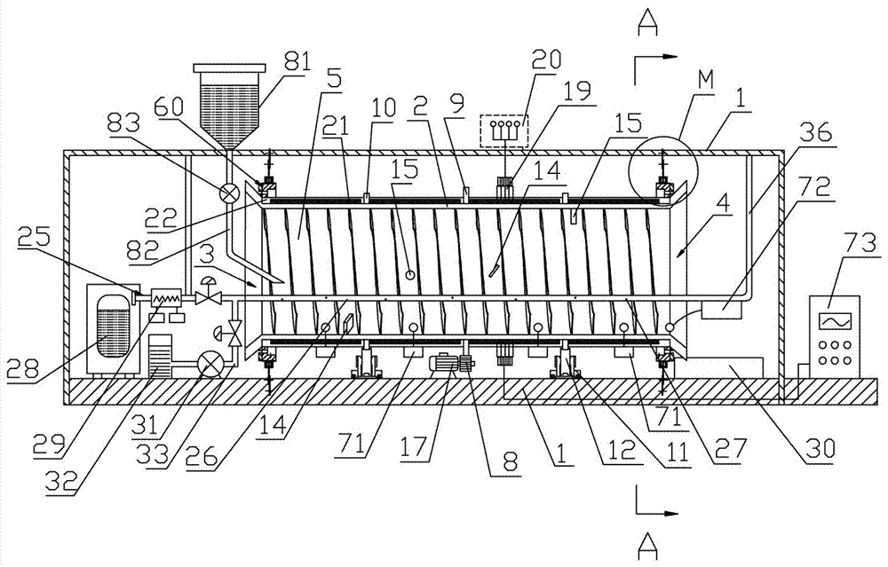
[0019] Such as figure 1As shown, the dynamic rotary sterilizer includes: a casing 1 and a cylinder 2 installed in the casing 1, and the two ends of the cylinder 2 are respectively provided with a feed inlet 3 and an outlet for materials to enter and exit the cylinder 2. The material port 4 is provided with a spiral guide groove 5 on the inner wall of the cylinder body 2, which can transport the material from the material inlet 3 to the material discharge port 4. The cylinder body 2 is movably supported in the casing 1 and is connected with the The drive assembly on the casing 1 is connected. Under the driving action of the drive assembly, the cylinder body 2 rotates around its own central axis, so that the material entering the rotating cylinder body 2 from the feed port 3 moves along the spiral guide groov...


PUM


Abstract

The invention discloses a dynamic rotary sterilizing cabinet in the field of sterilizing cabinets, which comprises: a casing and a cylinder body, the two ends of the cylinder body are respectively provided with feeding and discharging ports, and the inner wall of the cylinder is provided with a spiral guide Material trough, the cylinder body is movably supported in the casing and connected with the drive assembly, so that the material entering from the feed port gradually moves toward the discharge port along the spiral guide groove; the outer surface of the cylinder is covered with a heatable The heating plate of the cylinder body; the casing is equipped with a steam generating component, and its output end is connected with the multifunctional pipe inside the cylinder body, and there are several through holes on the multifunctional pipe, the water inlet of the water pump is connected with the water tank, and the outlet of the water pump The water pipe is connected with the multi-function pipe, and the clean water pressurized by the water pump can be sprayed out from the through hole on the multi-function pipe to wash the inner wall of the cylinder. The invention has the advantages of uniform heating of materials, no agglomeration, low energy consumption, automatic online cleaning, suitable for mass production and the like.

Description

technical field [0001] The invention relates to the field of sterilization cabinets, in particular to a dynamic rotary sterilization cabinet. Background technique [0002] Before the packaging process of products such as traditional Chinese medicine powder and granules, they need to be sterilized. At present, a kind of damp heat sterilization cabinet commonly used by production enterprises includes a cabinet body, which is equipped with a cabinet door, and inside the cabinet is a sterilization chamber. The sterilization chamber inside the body. Put the sterilization tray loaded with traditional Chinese medicine powder into the sterilization chamber of the sterilization cabinet before sterilization, then close the cabinet door, and the hot and humid steam generated by the high-temperature steam generator is passed into the sterilization chamber inside the cabinet through the pipeline room, so as to sterilize the Chinese medicine powder in the cabinet. When different materi...

Claims


Application Information

Patent Timeline
Patent Type & Authority Patents(China)
IPC IPC(8): A61L2/07A61L2/26B08B9/093
Inventor 陈远华吴云楚陈海迪刘朕火徐晶晶屈创
Owner JIANGSU SHENNONG AUTOCLAVE
Why Eureka
Try Eureka