
Tipper of scrap iron transfer trolley

A technology of turning machine and turning rack, which is applied in the direction of transportation and packaging, emptying containers, loading/unloading, etc., and can solve problems such as low efficiency, unfavorable enterprise work efficiency, and high labor intensity

Inactive Publication Date: 2015-07-15
SHANGHAI UNIV
View PDF5 Cites 1 Cited by
  • Summary
  • Abstract
  • Description
  • Claims
  • Application Information

AI Technical Summary

Problems solved by technology

It requires manual handling and transfer, which is labor-intensive and low-efficiency, which is not conducive to improving the work efficiency of the enterprise

Method used


Image

  • Tipper of scrap iron transfer trolley
  • Tipper of scrap iron transfer trolley
  • Tipper of scrap iron transfer trolley

Examples


Embodiment Construction

[0013] The present invention will be further described below in conjunction with the accompanying drawings and embodiments.

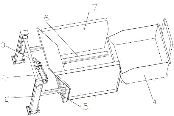
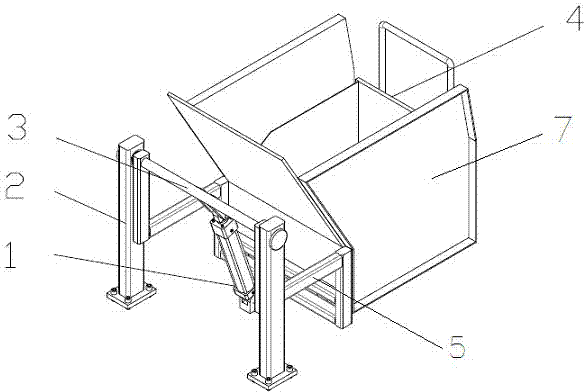
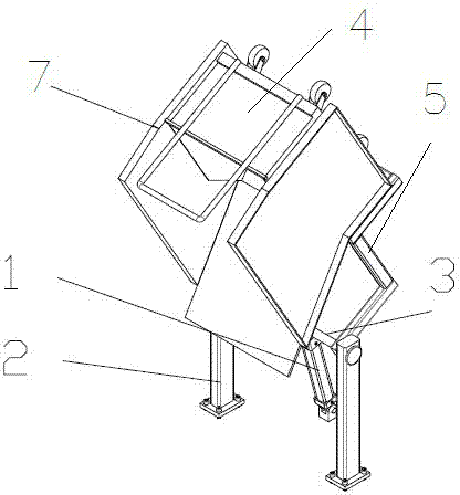
[0014] like Figure 1 to Figure 4 As shown, a turning machine for an iron filings transfer trolley is composed of an iron filings transfer trolley 4, a rotating shaft 3, a rotating shaft support 2, a hydraulic cylinder 1, a turning frame 5, a turning frame guide rail 6 and a cabinet 7; the rotating shaft support 2 Fixed on the ground, the rotating shaft 3 is hinged with the rotating shaft frame 2, the turning frame 5 is fixed on the rotating shaft 3, one end of the hydraulic cylinder 1 is fixed on the ground, and the other end is connected with the rotating shaft 3, the turning machine The frame guide rail 6 and the cabinet 7 are fixed on the turning frame 5, and the iron chip transfer trolley 4 is inserted into the bottom guide groove 8 of the iron filing transfer trolley 4 through the turning frame guide rail 6 to be connected and fixed.

[0015] Whe...


PUM


Abstract

The invention relates to a tipper of a scrap iron transfer trolley. The tipper consists of the scrap iron transfer trolley, a rotating shaft, a rotating shaft bracket, a hydraulic cylinder, a tipper rack, a tipper rack guide ail and a casing, wherein the rotating shaft rack is fixedly arranged on the ground; the rotating shaft is articulated with the rotating shaft rack; the tipper rack is fixedly arranged on the rotating shaft; one end of the hydraulic cylinder is fixedly arranged on the ground, and the other end of the hydraulic cylinder is connected with the rotating shaft; a tipper rack guide rail and the casing are fixedly arranged on the tipper rack; the scrap iron transfer trolley is inserted into a scrap iron transfer trolley bottom guide groove by virtue of the tipper rack guide rail so as to be connected and fixed. The tipper has the advantages of simple structure, high efficiency, easiness for regulation and control over inclination angle and height, high bearing capacity and the like.

Description

technical field [0001] The invention relates to a transfer device, in particular to a trolley turning machine used for turning waste iron filings in a numerical control machining center. Background technique [0002] At present, most of the mechanical products are finished by lathe processing. With the progress of the times, especially automation plus [0003] The use of machining equipment has improved the level of the entire machining industry. More and more CNC machining centers have gradually replaced general lathes. However, while the CNC machining center increases the speed of processing products, the speed of generating waste iron filings also increases. Iron filing waste is also a renewable resource. The collection and recycling of iron filings is an important task for enterprises. . At present, the receiving and transshipment of waste iron filings are mainly based on fixed receiving devices. It requires manual handling and transfer, which is labor-intensive and...

Claims


Application Information

Patent Timeline
IPC IPC(8): B65G65/23
CPCB65G65/23
Inventor 吕永福高施琛张永祥杨威邢科礼
Owner SHANGHAI UNIV
Learn More