Permanent magnet synchronous motor starting mechanism

A technology of permanent magnet synchronous motor and starting mechanism, which is applied to electric components, electrical components, electromechanical devices, etc., can solve problems such as increasing structural complexity, and achieve the effects of simple structure, large rotation angle and high starting success rate.

Inactive Publication Date: 2015-07-15
NINGBO ZHENGUAN ELECTRIC APPLIANCE
View PDF4 Cites 3 Cited by
  • Summary
  • Abstract
  • Description
  • Claims
  • Application Information

AI Technical Summary

Problems solved by technology

[0003] Aiming at the above-mentioned deficiencies in the prior art, the Chinese utility model patent No. ZL201420009740.7 provides a permanent magnet synchronous motor starting device in a double-start mode, which is provided with several socketed cam mechanisms, which can increase the speed to a certain extent. No load range during large start-up, but also increases the complexity of the structure

Method used


Image

  • Permanent magnet synchronous motor starting mechanism
  • Permanent magnet synchronous motor starting mechanism
  • Permanent magnet synchronous motor starting mechanism

Examples


Embodiment Construction

[0021] The present invention will be described in further detail below in conjunction with the accompanying drawings and specific embodiments.

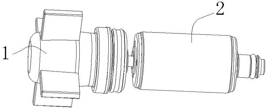
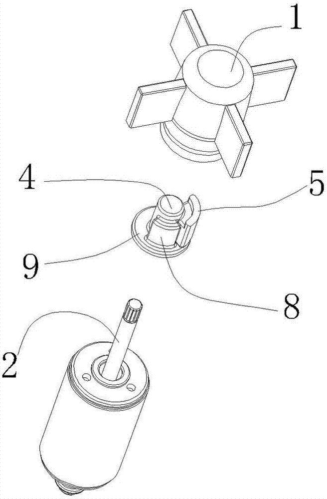
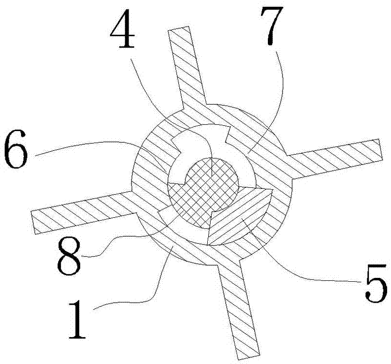
[0022] refer to Figure 1~Figure 4 , permanent magnet synchronous motor starting mechanism, including impeller 1, rotor 2, described impeller 1 has a mounting chamber 3, a driving sleeve 4 is arranged in the described mounting chamber 3, described rotor 2 and described driving sleeve 4 connected, so that the rotor 2 can drive the drive sleeve 4 to rotate. In this embodiment, the rotor 2 is inserted from the tail of the driving sleeve 4 and rigidly connected with the driving sleeve 4 as a whole.

[0023] There is a buffer member 5 between the drive sleeve 4 and the inner wall of the installation cavity 3, and the buffer member 5 interferes with the drive sleeve 4 in the radial direction, and the buffer member 5 and the The inner side walls of the installation cavity 3 interfere with each other in the radial direction, so that the dri...


PUM


Abstract

The invention discloses a permanent magnet synchronous motor starting mechanism. The permanent magnet synchronous motor starting mechanism comprises an impeller and a rotor, wherein the impeller is provided an installing cavity, the installing cavity is internally provided with a driving sleeve, the rotor is connected with the driving sleeve, and therefore the rotor can drive the driving sleeve to rotate; a buffering piece is installed between the driving sleeve and the inner wall of the installing cavity, the buffering piece and the driving sleeve are mutually interfered in the radial direction, the buffering piece and the inner side wall of the installing cavity are mutually interfered in the radial direction, and therefore the driving sleeve is driven to rotate and drive the buffering piece to rotate, and then the buffering piece drives the impeller to rotate. According to the permanent magnet synchronous motor starting mechanism, the buffering piece and the driving sleeve are mutually interfered in the radial direction, the buffering piece and the inner side wall of the installing cavity are mutually interfered in the radial direction, and therefore the driving sleeve is driven to rotate and drive the buffering piece to rotate, and then the buffering piece drives the impeller to rotate, so that the purpose of starting is achieved, the rotating angle of the buffering piece is large, the starting success rate is high, the damage to a motor is small, and the structure is simple.

Description

technical field [0001] The invention relates to a starting mechanism of a permanent magnet synchronous motor. Background technique [0002] The existing permanent magnet synchronous motor starting mechanism generally drives the buffer member fixed on the impeller through the rotor, and this type of structure is fixed on the impeller due to the buffer member. The no-load range of the rotor at start-up is the difference between the sum of the angles occupied by the driver, the buffer, and the impeller limiting boss and the angle of a circle. As we all know, the synchronous motor has the characteristics of small starting torque, the smaller the no-load range during the starting process, the worse the starting reliability. [0003] Aiming at the above-mentioned deficiencies in the prior art, the Chinese utility model patent No. ZL201420009740.7 provides a permanent magnet synchronous motor starting device in a double-start mode, which is provided with several socketed c...

Claims


Application Information

Patent Timeline
Patent Type & Authority Applications(China)
IPC IPC(8): H02K7/118
Inventor 张建堂戎海波汪立欢
Owner NINGBO ZHENGUAN ELECTRIC APPLIANCE
Why Eureka
Try Eureka