Method for quick positioning of fiber core fault

A fiber core and fault technology, applied in optical fiber transmission, electromagnetic wave transmission system, electrical components, etc., can solve the problems of low routing analysis efficiency, unintuitive, non-standard record of optical cable link connection relationship, etc.

Active Publication Date: 2015-07-15
北京千禧维讯科技有限公司
View PDF7 Cites 16 Cited by
  • Summary
  • Abstract
  • Description
  • Claims
  • Application Information

AI Technical Summary

Problems solved by technology

[0008] In view of this, the present invention provides a method for quickly locating fiber core faults, which is used to solve the problems of incomplete

Method used


Image

  • Method for quick positioning of fiber core fault
  • Method for quick positioning of fiber core fault
  • Method for quick positioning of fiber core fault

Examples


Embodiment 1

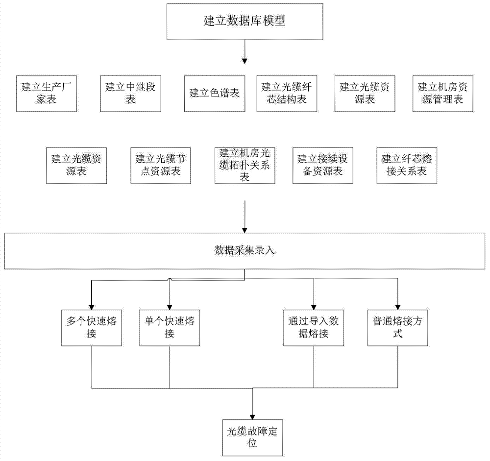
[0048] Embodiment 1. This method is used to perform fiber core splicing for an optical cable network system composed of a computer room, splicing equipment and optical cables. The flow chart of the method is as follows figure 1 As shown, it specifically includes the following steps:

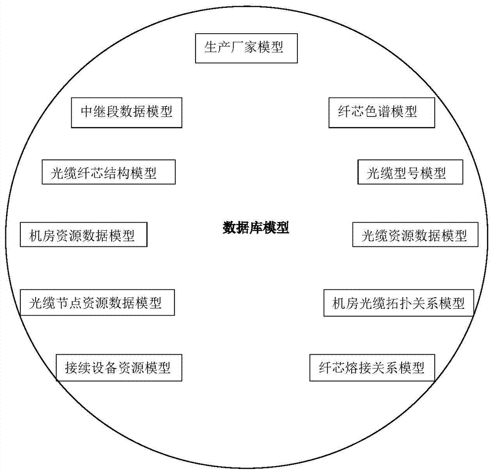
[0049] Step 1. Establish a database model, wherein the database model includes 11 types of models, such as figure 2 As shown, they are: manufacturer model, relay section data model, fiber core chromatogram model, optical cable core structure model, optical cable model model, computer room resource data model, optical cable resource data model, optical cable node resource data model, and optical cable topology in the computer room Relationship model, splicing equipment resource model and fiber core splicing relationship model;

[0050] The manufacturer model is used to store the manufacturer information of all optical cables, and each piece of manufacturer information includes the following item...


PUM


Abstract

The invention discloses a method for quick positioning of a fiber core fault. A system is used for performing fiber core fault quick-positioning on an optical cable network system comprising a machine room, connection equipment and optical cables. The method comprises the steps that firstly, for 11 data models of an optical cable fiber core connection relation, uniform, normal and standard management to optical cable network resource data is realized; for a practical optical cable network, actual measurement is performed, so as to obtain attribute data in network resources and topological relation data among the resources; the data is stored into a database model established in the first step, and geographic data in the network resources is obtained at the same time; then a connection relation forming link of an optical cable fiber core is established; after a fault distance and a fiber core in failure are measured through an optical time domain reflectometer, a route relation among the optical cables of the whole link can be established by taking the tendency of the fiber core as a basis, and a fault point can be quickly and accurately positioned.

Description

technical field [0001] The invention belongs to the technical field of optical cable network resource management, and in particular relates to a method for rapidly locating fiber core faults. Background technique [0002] With the continuous increase of optical cable network resources, the connection relationship between optical cables becomes more and more complicated. Engineers mainly use Excel files to record the corresponding relationship between the cores of optical cables, and cannot view the routing relationship of the entire link. [0003] The current optical cable resource management system can only view the connection relationship of adjacent optical cables, but cannot view the routing relationship of the entire link, and it is difficult to quickly locate the information resources of the corresponding link. [0004] Excel files have poor real-time performance, are difficult to update or save in time, and are difficult to query. And it cannot be shared with the co...

Claims


Application Information

Patent Timeline
IPC IPC(8): H04B10/25H04B10/075
Inventor 田力唐节班黎明吴小兵欧阳美珍任海蛟吴伟青
Owner 北京千禧维讯科技有限公司
Why Eureka
Try Eureka