
Gas discharge system for a refrigeration compressor and a refrigeration compressor

A refrigeration compressor and gas discharge technology, which is applied in the field of compressors, can solve problems such as power loss, and achieve the effects of reducing power loss, reducing heat exchange, and reducing pressure transients

Active Publication Date: 2015-07-15
EMPRESA BRASILEIRA DE COMPRESSORES SA (EMBRACO)
View PDF5 Cites 4 Cited by
  • Summary
  • Abstract
  • Description
  • Claims
  • Application Information

AI Technical Summary

Problems solved by technology

In these configurations, the gas reaching the discharge chamber undergoes a pressure reduction, diffuses in a random and turbulent manner inside the discharge chamber, which leads to power loss in the area of ​​the valve plate

Method used


Image

  • Gas discharge system for a refrigeration compressor and a refrigeration compressor
  • Gas discharge system for a refrigeration compressor and a refrigeration compressor
  • Gas discharge system for a refrigeration compressor and a refrigeration compressor

Examples


Embodiment Construction

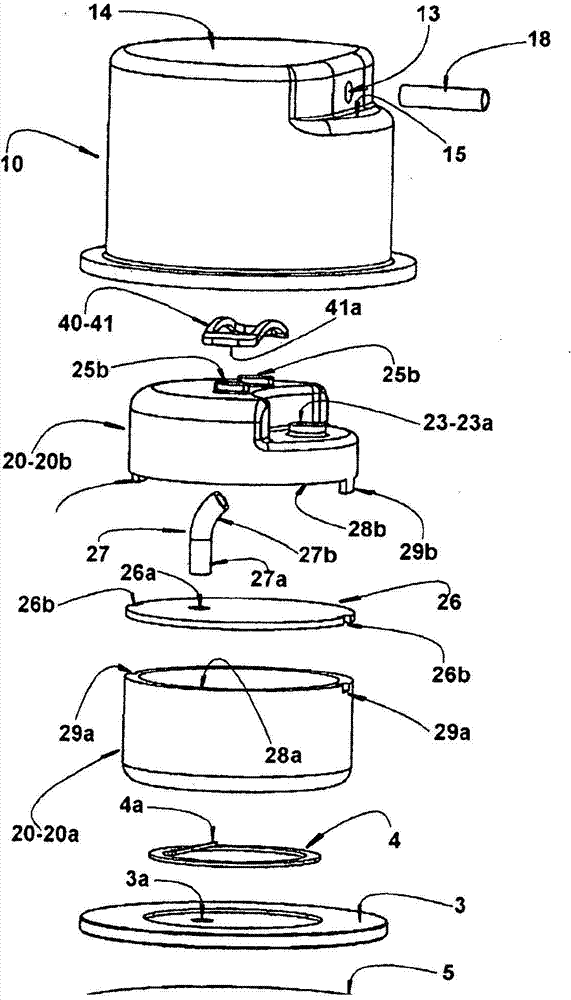
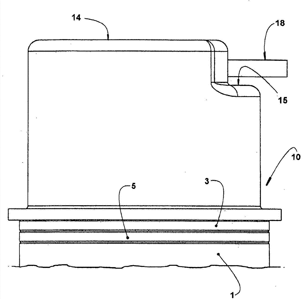
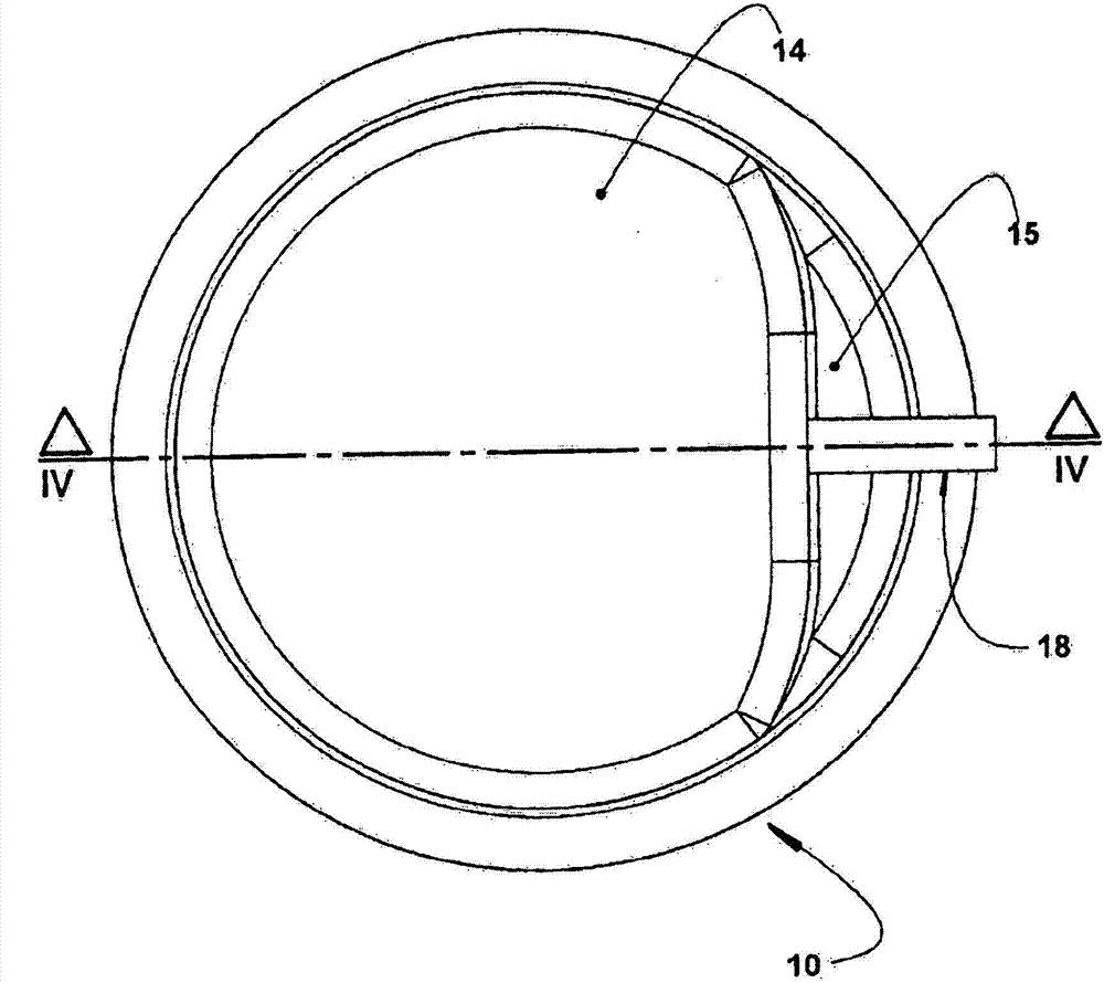
[0018] The present invention will describe a hermetic reciprocating type refrigeration compressor, and said refrigeration compressor includes a motor-compressor assembly (not shown), said refrigeration compressor includes a cylinder crankcase 1 (in Figure 4 Partially shown in ), the cylinder crankcase defines a cylinder 2 inside which a piston is axially displaced by the action of a rotary or linear electric motor (not shown).

[0019] The cylinder crankcase may be constructed from any suitable metal alloy known in the art.

[0020] The cylinder 2 has an open end through which the piston is received, and an opposite end closed by the valve plate 3 (at Figure 4 is shown in ), against which valve plate 3 delimits a compression chamber C with the cylinder 2 is seated a generally metallic cylinder head 10 . The valve plate 3 is constructed of a metal alloy so as to operate with at least one suction valve (not shown), facing the interior of the cylinder 2, and at least one disch...


PUM


Abstract

The compressor comprises: a cylinder crankcase (1) defining a cylinder (2) which is closed by a valve plate (3) provided with at least one discharge orifice (3a) associated with a discharge valve (4) and defining, with the cylinder (2), a compression chamber (C); a cylinder cap (10) seated against the valve plate (3) and inside which is defined a discharge chamber (11). The system comprises an accelerating means (AM) mounted in the interior of the discharge chamber (11) and secured to at least one of the parts of cylinder cap (10) and valve plate (3), in order to receive the entire flow of refrigerant gas released through the discharge orifice (3a), accelerating said gas flow and producing an instantaneous reduction in the pressure gradient between the upstream and downstream sides of the discharge valve (4), in the moment the latter opens.

Description

technical field [0001] The present invention relates to a gas discharge system for a refrigeration compressor, for example a hermetically reciprocating refrigeration compressor, in particular driven by a linear motor, and to a compressor comprising said system. Background technique [0002] One of the sources of power and mass efficiency loss in compressors is the gas discharge system. In a gas discharge system where the movement of one or more discharge valves is regulated (ie, the discharge valve opens or closes at a desired moment and with low vibration), one minimizes the flow due to gas flow through the valve by eliminating or reducing backflow. The resulting power loss improves mass efficiency. [0003] The pressure upstream and downstream of the discharge valve are some of the variables that define its operating dynamics. Such variables depend on the refrigerant gas, the operating conditions of the compressor, the design of the discharge orifice, and in particular o...

Claims


Application Information

Patent Timeline
Patent Type & Authority Applications(China)
IPC IPC(8): F04B39/00F04B39/10F04B39/12
CPCF04B39/125F04B39/123F04B39/10F04B39/0055F04B53/1037F04B53/001F04B53/1085F16K15/16F04B53/16F04B39/064F04B39/14F04B39/121F04B53/007F04B39/0061F04B39/06F04B39/0027
Inventor D·E·B·利利T·瓦杰兹克
Owner EMPRESA BRASILEIRA DE COMPRESSORES SA (EMBRACO)
Features
  • Generate Ideas
  • Intellectual Property
  • Life Sciences
  • Materials
  • Tech Scout
  • Unparalleled Data Quality
  • Higher Quality Content
  • 60% Fewer Hallucinations
Learn More