positioning claw

A technology of positioning claws and positioning blocks, which is applied in the direction of positioning devices, metal processing equipment, feeding devices, etc., can solve the problems of consuming manpower, material resources, financial resources and time, increasing enterprise costs, and poor versatility, so as to reduce manual operations, The effect of extending the service life and improving versatility

Active Publication Date: 2017-01-04
苏州泰克诺机电有限公司
View PDF7 Cites 0 Cited by
  • Summary
  • Abstract
  • Description
  • Claims
  • Application Information

AI Technical Summary

Problems solved by technology

[0002] In the production process of automobile seats, the parts to be processed in each production line often need to be clamped and fixed before being sent to the mold for subsequent processing, which also puts higher requirements on the clamping and positioning device, and each mold itself The structure and the shape of the workpiece to be processed are different, and the clamping and positioning device in the prior art is poor in versatility. Therefore, when using different molds to process different workpieces to be processed, it is often necessary to use different clamping and positioning devices. The clamping and positioning device not only increases the production cost of the enterprise, but also the design of each clamping and positioning device consumes a lot of manpower, material resources, financial resources and time of the enterprise, which further increases the cost of the enterprise. , the corresponding clamping and positioning device is also difficult to use in other molds, causing greater losses to the enterprise; at the same time, due to the needs of automated production, it is also required that the clamping and positioning device can fully cooperate with the mold to achieve maximum production efficiency , so there is a need for a clamping and positioning device that can fully fit the mold and has greater versatility

Method used


Image

  • positioning claw
  • positioning claw

Examples


Embodiment 1

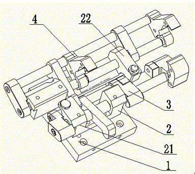
[0025] A positioning claw disclosed by the present invention, as attached Figure 1-2 As shown, it includes a base 1, which is provided with several screw holes for installing the positioning claws on the mold, and also includes a workpiece positioning mechanism 2, a first clamp telescopic mechanism 3, The second clamp telescopic mechanism 4.

[0026] Wherein, the workpiece positioning mechanism 2 includes a first U-shaped positioning block 21 and a second U-shaped positioning block 22 arranged on the base 1 through a bolt gap, and the two are parallel to each other, and they cooperate with each other to form a A placement surface for placing workpieces to be processed; the first side branch 26 of the first U-shaped positioning block 21 is provided with a limit surface 24 that restricts the upward rotation of the first clamp telescopic mechanism 3; furthermore, in order to treat The workpiece is positioned, and at least one positioning pin 23 is arranged on the upper end surf...

Embodiment 2

[0032] The overall mechanism of this embodiment is the same as that of Embodiment 1, and the difference is that: the workpiece positioning device 2 is a positioning block with a U-shaped cross section, and a positioning pin 23 is arranged on it; the first clamp is telescopic Mechanism 3 includes a first rotating shaft 31 and a first clamp 32, and the first rotating shaft 31 runs through the two side branches of the positioning block and the first clamping clamp 32; A first torsion spring 35 is arranged between two side branches and one of the remaining side branches, thereby forming a reset mechanism of the first clamp telescopic mechanism 3; the second clamp telescopic mechanism 4 includes a second linkage rod 41, a second A rotating shaft 42, a linear guide rail 43 and two second clamps 44, the second linkage rod 41 is connected with the first clamp 32 to form a linkage mechanism, and the second rotating shaft 42 and the linear guide rail 43 respectively pass through the sec...

Embodiment 3

[0035] The overall structure of this embodiment is the same as that of the above-mentioned embodiment 1, and the difference is that: the number of the first clamps 32 is two, and they are movably arranged on the first rotating shaft 31, preferably in this embodiment Because they are respectively fixed on the two ends of the first rotating shaft 31 ; meanwhile, the two second clamps 44 are movably arranged on the second rotating shaft 42 and the linear guide rail 43 . In actual application, the fixing position of each clamp can be adjusted according to the different shapes of different workpieces, so that each clamp can better cooperate to fix the workpiece.


PUM


Abstract

The invention discloses a locating detent. The locating detent comprises a base, a to-be-machined workpiece locating mechanism, a first clamp telescopic mechanism and a second clamp telescopic mechanism, wherein the to-be-machined workpiece locating mechanism is arranged on the base, and the first clamp telescopic mechanism and the second clamp telescopic mechanism are arranged on the to-be-machined workpiece locating mechanism, form a linkage mechanism between and are opened outwards or contracted inwards at the same time under the action of external force. The locating detent is ingenious in design and easy to operate, and can be installed and replaced on different dies fast and conveniently and locate to-be-machined workpieces fast and accurately; as the whole tool can be adjusted according to needs of the different workpieces, the generality is improved; as the linkage mechanism formed between the clamp telescopic mechanisms effectively uses the connection relation among all components, and power provided by a die is combined, opening and closing of the locating detent are matched with the whole automatic die, manual operation is reduced, and the working efficiency is improved.

Description

technical field [0001] The invention relates to a clamping and positioning device for a workpiece to be processed, in particular to a positioning claw for a workpiece to be processed. Background technique [0002] In the production process of automobile seats, the parts to be processed in each production line often need to be clamped and fixed before being sent to the mold for subsequent processing, which also puts higher requirements on the clamping and positioning device, and each mold itself The structure and the shape of the workpiece to be processed are different, and the clamping and positioning device in the prior art is poor in versatility. Therefore, when using different molds to process different workpieces to be processed, it is often necessary to use different clamping and positioning devices. The clamping and positioning device not only increases the production cost of the enterprise, but also the design of each clamping and positioning device consumes a lot of ...

Claims


Application Information

Patent Timeline
Patent Type & Authority Patents(China)
IPC IPC(8): B21D43/10
CPCB21D43/003
Inventor 曹义军
Owner 苏州泰克诺机电有限公司
Why Eureka
Try Eureka