A manufacturing fixture and manufacturing method of moving iron unit square iron

A manufacturing method and moving iron technology, applied in manufacturing tools, auxiliary devices, laser welding equipment, etc., can solve problems such as low production efficiency and poor product quality, and achieve the effects of good applicability, good quality, and improved production efficiency

Active Publication Date: 2016-05-18
CHANGZHOU AMT
View PDF6 Cites 0 Cited by
  • Summary
  • Abstract
  • Description
  • Claims
  • Application Information

AI Technical Summary

Problems solved by technology

[0005] The purpose of the present invention is to overcome the shortcomings of low production efficiency and poor product quality of the square iron of the existing moving iron unit, and provide a manufacturing fixture and manufacturing method for the square iron of the moving iron unit. Adopting the technical scheme of the present invention, laser welding It replaces the traditional ultrasonic welding and adopts special fixtures to improve the assembly efficiency of the sheet body. The assembly of the sheet body is more convenient. 10 or more square irons can be welded at one time, which greatly improves the production efficiency of the square iron. ;In addition, the multi-piece body is easy to locate, and the laser welding has no contact force. After the square iron is made, the dimensional change is small and the quality is good, which can be used for mass production

Method used


Image

  • A manufacturing fixture and manufacturing method of moving iron unit square iron
  • A manufacturing fixture and manufacturing method of moving iron unit square iron
  • A manufacturing fixture and manufacturing method of moving iron unit square iron

Examples


Embodiment

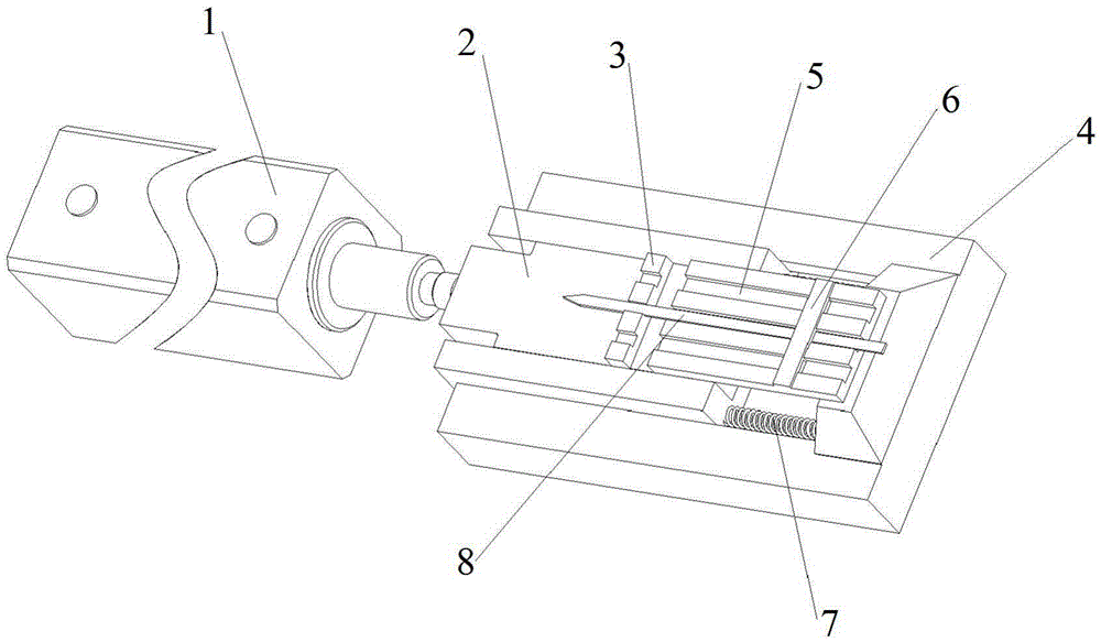
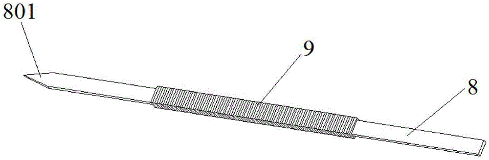
[0039] combine figure 1 and figure 2 , a manufacturing jig for moving iron unit square iron in this embodiment includes a cylinder 1, a slider 2, a slider 4 and a fixed core 8, the cylinder 1 is connected to the slider 2, and the slider 2 and the slider 4 are slidably matched , under the action of the cylinder 1, the slider 2 can slide in the slider 4; the slider 2 is fixedly provided with a push block 3, the rear end of the slider 4 is fixedly provided with a positioning plate 5, and the positioning plate 5 is provided with a stopper 6 , the push block 3 and the positioning plate 5 are respectively provided with positioning grooves on the same straight line, the stopper 6 is provided with a positioning hole on the same line as the above-mentioned positioning groove, the positioning groove on the push block 3 and the stopper 6 The size of the positioning hole on the positioning plate 5 is slightly larger than the size of the fixed core 8, which is convenient for the install...


PUM


Abstract

The invention discloses a manufacturing jig and a manufacturing method for moving-iron unit square iron and belongs to the field of tool jigs. The manufacturing jig for the moving-iron unit square iron comprises an air cylinder, a slide block, a slide base and fixing cores, wherein the air cylinder is connected with the slide block, the slide block is matched with the slide base in a sliding mode, a push block is fixedly arranged on the slide block, a locating plate is fixedly arranged at the rear end of the slide base, a stop block is arranged on the locating plate, the push block and the locating plate are provided with locating grooves on the same straight line respectively, the stop block is provided with a locating hole located on the same straight line with the locating grooves, the fixing cores are installed in the locating grooves and the locating hole, and the fixing cores are used for clamping and fixing a plurality of sheet bodies installed on the fixing cores in a penetrating mode between the push block and the stop block to achieve laser welding. The invention further discloses the manufacturing method for the moving-iron unit square iron. The manufacturing jig and the manufacturing method for moving-iron unit square iron use the laser welding to replace traditional ultrasonic welding, meanwhile, the special jig is adopted, and the manufacturing efficiency of the square iron is greatly improved; in addition, the laser welding has no contact acting force, and therefore the size change is small after the square iron is manufactured.

Description

technical field [0001] The present invention relates to a manufacturing equipment and manufacturing process of moving iron unit square iron, more specifically, relates to a manufacturing jig and manufacturing method of moving iron unit square iron. Background technique [0002] The magnetic driving mechanism of the moving iron unit is mainly composed of a balanced armature, a square iron (yoke iron), an induction coil and a permanent magnet. The permanent magnet is symmetrically arranged in the square iron to form a vibration space for the balanced armature. The balanced armature passes through In the middle of the two permanent magnets, one end is provided with an induction coil, and the other end is connected to the diaphragm through a conductive rod. The structure of the moving iron unit is very small, so the magnetic driving mechanism inside it is also very small. The square iron forming the magnetic driving mechanism is a cuboid structure with a rectangular through hole...

Claims


Application Information

Patent Timeline
Patent Type & Authority Patents(China)
IPC IPC(8): B23K26/70B23K37/04B23K26/21
CPCB23K26/20B23K37/04
Inventor 魏鹏孟献振曾伟
Owner CHANGZHOU AMT
Why Eureka
Try Eureka