A Simple Fixture for Machining Parallel Groove of Slider

A technology of tooling fixtures and parallel grooves, which is applied in the direction of manufacturing tools, metal processing equipment, metal processing machinery parts, etc., can solve problems such as inability to guarantee processing dimensional stability, affect processing accuracy, correct operation waste force, etc., and achieve shortening auxiliary Man-hours, simplification of operations, and weight reduction effects

Active Publication Date: 2017-10-31
SHANGHAI DAZHONG XIANGYUAN POWER SUPPLY
View PDF6 Cites 0 Cited by
  • Summary
  • Abstract
  • Description
  • Claims
  • Application Information

AI Technical Summary

Problems solved by technology

However, during the use of the general fixture, it is not easy to clamp the slider, and it is easy to produce displacement deviation, which affects the processing accuracy, that is, it is difficult to ensure parallelism between the small groove and the large groove.
This requires a correction every time a piece is clamped, and the correction operation is wasteful and time-consuming, resulting in the auxiliary man-hour of clamping greatly exceeding the effective processing time, resulting in low processing efficiency, and the stability of the processing size cannot be guaranteed.

Method used


Image

  • A Simple Fixture for Machining Parallel Groove of Slider
  • A Simple Fixture for Machining Parallel Groove of Slider

Examples


Embodiment

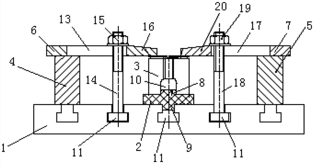
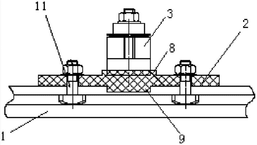
[0025] Such as Figure 1-2 As shown, a simple tooling fixture for machining parallel grooves of sliders, the fixture includes a convex positioning block 2 arranged on a machine tool 1, a slider 3 to be processed arranged on the convex positioning block 2, symmetrically arranged on The first machine block 4 and the second machine block 5 on the left and right sides of the convex positioning block 2 are respectively arranged on the first machine block 4 and the second machine block 5 and are used for pressing The first press plate 6 and the second press plate 7 of the slide block 3 to be processed, the convex positioning block 2 are fixedly connected with the machine tool 1 along the feed direction of the machine tool 1, the first press plate 6 and the second press plate 7 are arranged oppositely, and the slide to be processed Block 3 is compressed and fixed on the convex positioning block 2.

[0026] Wherein, the upper and lower surfaces of the convex positioning block 2 are r...


PUM


Abstract

The invention relates to a simple work fixture used for machining parallel grooves of a sliding block. The simple work fixture comprises a convex positioning block, the sliding block to be machined, a first machine tool cushion block, a second machine tool cushion block, a first pressing plate and a second pressing plate, wherein the convex positioning block is arranged on a machine tool; the sliding block to be machined is arranged on the convex positioning block; the first machine tool cushion block and the second machine tool cushion block are symmetrically arranged at the left side and the right side of the convex positioning block respectively; the first pressing plate and the second pressing plate are arranged on the first machine tool cushion block and the second machine tool cushion block respectively and are used for pressing the sliding block to be machined. The convex positioning block is fixedly connected with the machine tool in the feed direction of the machine tool. The first pressing plate and the second pressing plate are oppositely arranged and fix the sliding block to be machined to the convex positioning block in a pressing mode. Compared with the prior art, the simple work fixture is simple and compact in structure, economical, practical and capable of achieving direct clamping without correction, so the subsidiary time is greatly shortened, operation is simplified, machining efficiency is improved, and the stability of machining quality is ensured.

Description

technical field [0001] The invention belongs to the technical field of mechanical processing, and relates to a tooling fixture, in particular to a simple tooling fixture for machining parallel grooves of a slider. Background technique [0002] During the processing of the traditional parallel groove of the slider, the large groove of the slider is processed first, and then the slider is fixed by using a universal fixture, and then the small groove is processed. However, during the use of the general fixture, it is not easy to clamp the slider, and it is easy to produce displacement deviation, which affects the processing accuracy, that is, it is difficult to ensure parallelism between the small groove and the large groove. This requires a correction every time a piece is clamped, and the correction operation is wasteful and time-consuming, resulting in the auxiliary man-hours of clamping greatly exceeding the effective processing man-hours, resulting in low processing effici...

Claims


Application Information

Patent Timeline
Patent Type & Authority Patents(China)
IPC IPC(8): B23Q3/06
CPCB23Q3/06B23Q2703/02
Inventor 朱方磊戴豪丁贞保苏航
Owner SHANGHAI DAZHONG XIANGYUAN POWER SUPPLY
Why Eureka
Try Eureka