
Flexible clamping claw

A flexible clamping and claw technology, applied in the field of agricultural and forestry equipment, can solve the problems of difficulty in implementation and easy winding, etc., and achieve the effects of guaranteed success rate, convenient operation, and simple device structure

Active Publication Date: 2015-07-22
北京市农林科学院智能装备技术研究中心
View PDF7 Cites 3 Cited by
  • Summary
  • Abstract
  • Description
  • Claims
  • Application Information

AI Technical Summary

Problems solved by technology

In addition, the above-mentioned driving method requires the arrangement of air pipes and wires, which is prone to entanglement, which brings difficulties to the realization of the operation mode of the rotary table with multiple grippers

Method used


Image

  • Flexible clamping claw
  • Flexible clamping claw
  • Flexible clamping claw

Examples


Embodiment Construction

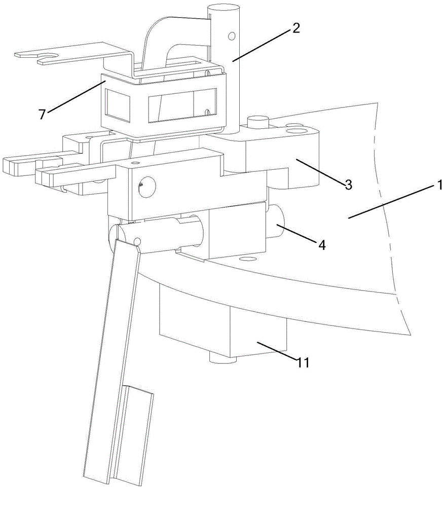
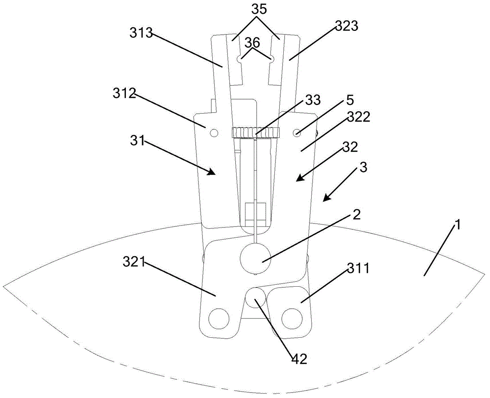
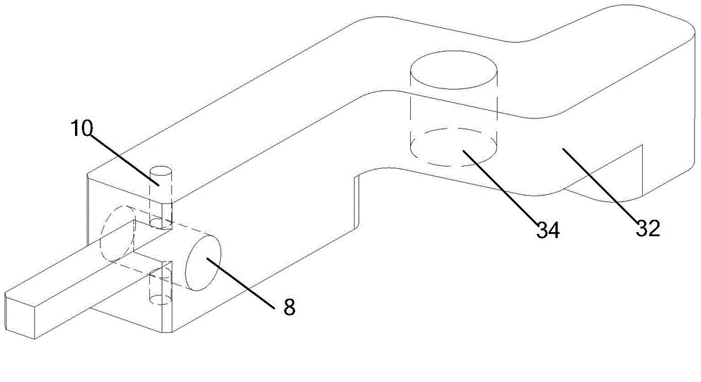
[0020] figure 1 It is a schematic structural diagram of the flexible clamping gripper provided by Embodiment 1 of the present invention, Figure 2a It is a schematic structural diagram of a clamping device for a flexible clamping gripper provided in Embodiment 1 of the present invention, Figure 2b Another structural schematic diagram of the clamping device for the flexible clamping gripper provided by Embodiment 1 of the present invention, image 3 Schematic diagram of the structure of the pushing device for the flexible clamping claw provided in Embodiment 1 of the present invention; Figure 1~3 As shown, the flexible clamping gripper provided by this embodiment includes: a base 1, a fixed shaft 2 vertically and fixedly installed through the base 1, and also includes: a clamping device 3 sleeved on the fixed shaft 2, and for The pushing device 4 that makes clamping device 3 open and close; Wherein, clamping device 3 comprises: left clip body 31, right clip body 32, extensi...


PUM


Abstract

The invention provides a flexible clamping claw which comprises a base, a perpendicular fixed shaft penetrating through the base, a clamping device arranged on the fixed shaft in a sleeving mode, and a push device for opening and closing the clamping device. The clamping device comprises a left clamping body, a right clamping body and a tension spring, wherein the tail portion of the left clamping body and the tail portion of the right clamping body are arranged on the fixed shaft in a crossed and sleeving mode and rotate in the axial direction of the fixed shaft, and the two ends of the tension spring are fixedly connected with the arm portion of the left clamping body and the arm portion of the right clamping body respectively. The push device comprises a push rod and a limiting rod, wherein a slide groove which is through and extends in the length direction of the push rod is formed in the push rod, and the fixed shaft perpendicularly penetrates through the slide groove. The first end of the push rod is fixedly provided with the limiting rod which is parallel to the fixed shaft, the limiting rod is clamped in a space outside the crossed point of the tail portion of the left clamping body and the tail portion of the right clamping body, the slide groove is used for making the push rod reciprocate within the stroke range of the slide groove, the limiting rod is separated from or clamped in the crossed space of the tail portion of the left clamping body and the tail portion of the right clamping body, and therefore the left clamping body and the right clamping body can be opened and closed.

Description

technical field [0001] The invention relates to agricultural and forestry equipment technology, in particular to a flexible clamping claw. Background technique [0002] With the development of agricultural and forestry equipment technology, modern agriculture has higher and higher requirements for the performance of agricultural and forestry equipment. [0003] For example, in the production process of grafted seedlings, it is required to ensure the safe clamping of the seedlings to ensure the survival rate of the grafted seedlings. Therefore, it is necessary for the clamping claws of the grafting machine to use proper force during the process of clamping the grafted seedlings so as not to damage the grafted seedlings. [0004] However, the seedling clamping link of the existing grafting machine generally uses pneumatic fingers, stepping motors, etc. as the driving parts of the clamping claws, and the pneumatic fingers and stepping motors will continue to provide clamping f...

Claims


Application Information

Patent Timeline
IPC IPC(8): B25J15/08A01G1/06
Inventor 姜凯王秀范鹏飞张春凤冯青春
Owner 北京市农林科学院智能装备技术研究中心
Learn More