Automatic board splicing machine with swaging function

An automatic splicing machine and functional technology, applied in the field of wood processing machinery, can solve the problems of unfavorable pushing plate action cylinder energy consumption, large friction resistance, large downward resistance, etc., so as to improve the overall splicing effect and reduce the contact area. , the effect of reducing the downside resistance

Inactive Publication Date: 2015-07-22
永州浙南竹木有限公司
View PDF6 Cites 6 Cited by
  • Summary
  • Abstract
  • Description
  • Claims
  • Application Information

AI Technical Summary

Problems solved by technology

Although this patent solution can realize the technical effect of the penultimate 6th line to the penultimate line 3rd line on the first page of the instruction manual, since the pushing mechanism only consists of a pair of pushing plate action cylinders (patent optional oil cylinders) and a The pusher plate of the plate action cylinder is composed of a pusher plate connected to the end of the cylinder column, so in the actual use process, the pusher mechanism will inevitably produce the following technical problems: First, because the pusher plate is relatively lengthy (usually larger than equal to 122㎝), and because the middle part of the length direction of the pusher plate facing the side of the pusher plate action cylinder is connected to the end of the pusher plate action cylinder column, the cylinder column protrudes out of the cylinder when the push plate action When driving the pusher plate to move, the pusher plate behaves as a negative movement, that is, a passive movement. It is difficult to guarantee the overall movement effect of the pusher plate, that is to say, it is difficult to ensure the overall synchronous movement of the two ends and the middle of the entire pusher plate. effect, whic

Method used


Image

  • Automatic board splicing machine with swaging function
  • Automatic board splicing machine with swaging function
  • Automatic board splicing machine with swaging function

Examples


Embodiment Construction

[0020] In order to enable the examiners of the patent office, especially the public, to understand the technical essence and beneficial effects of the present invention more clearly, the applicant will describe in detail the following in the form of examples, but none of the descriptions to the examples is an explanation of the solutions of the present invention. Any equivalent transformation made according to the concept of the present invention which is merely formal but not substantive shall be regarded as the scope of the technical solution of the present invention.

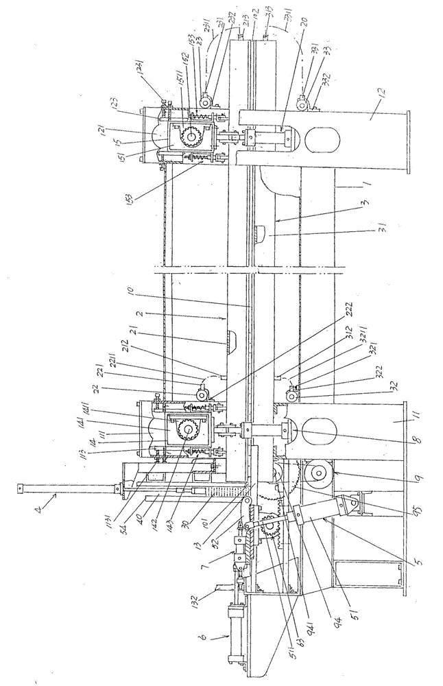
[0021] In the following descriptions, all concepts involving up, down, left, right, front and back are for figure 1 As far as the positional state shown is concerned, it should not be understood as a special limitation of the present invention.

[0022] See figure 1 , a frame 1 is given, the left end of the frame 1 is fixed between a pair of frame left columns 11 that are set facing each other and are suppor...


PUM


Abstract

The invention provides an automatic board splicing machine with a swaging function and belongs to the technical field of woodworking machines. The automatic board splicing machine comprises a machine frame, an upper heating mechanism, a lower heating mechanism, a board pressing mechanism, a turning mechanism and a pushing mechanism, and is characterized in that the pushing mechanism comprises a pair of pushing plate actuation cylinders, a pushing plate and a pair of pushing plate synchronization devices; the upper heating mechanism comprises a set of upper heating pipes, an upper heating pipe heating medium lead-in header pipe and an upper heating pipe heating medium lead-out header pipe; the lower heating mechanism comprises a set of lower heating pipes, a lower heating pipe heating medium lead-in header pipe and a lower heating pipe heating medium lead-out header pipe; a board row moving channel is formed between the upper heating pipes and the lower heating pipes; the board pressing mechanism comprises a supporting beam, a pair of pressing actuation cylinder fixing frames, a pair of gate lath abutting beams, a set of gate laths, a board pressing strip and a pair of board pressing strip actuation cylinders, and the cross section of the gate laths is in a V shape. The overall movement effect is good, resistance borne by the pushing plate is reduced, the splicing combination effect is good, and descending resistance borne by boards is reduced.

Description

technical field [0001] The invention belongs to the technical field of wood processing machinery, and in particular relates to an automatic jigsaw machine with a pressing function. Background technique [0002] The function of the jigsaw machine mentioned above is to splice the slats of different lengths but with the same thickness and width produced in the process of producing wood products in the wood product industry into such as 122 (width) × 244 (length) The entire board is used as a board for furniture, cabinets and interior decoration. Its positive significance lies in saving precious wood resources. [0003] The technical information about the jigsaw machine can be seen in the published Chinese patent literature, such as the authorized announcement number CN2265880Y recommending a "heating jigsaw machine". Both ends of the heating tube are provided with support rods, and the heating tube is placed on the upper part of the frame (patent called the base) in a suspende...

Claims


Application Information

Patent Timeline
IPC IPC(8): B27D3/00
CPCB27D1/10B27D3/00B27D5/00
Inventor 周刚
Owner 永州浙南竹木有限公司
Why Eureka
Try Eureka