Explosion-proof component and oil-gas recovery system for oil-gas recovery system

A technology of oil and gas recovery system and components, which is applied in the direction of engine components, containers, functional valve types, etc., can solve the problems of potential safety hazards, oil storage tank combustion, explosion, etc., and achieve the effect of low maintenance cost and improved safety

Active Publication Date: 2017-03-01
上海森鑫新能源科技有限公司
View PDF6 Cites 0 Cited by
  • Summary
  • Abstract
  • Description
  • Claims
  • Application Information

AI Technical Summary

Problems solved by technology

[0004] The purpose of the present invention is to provide a flameproof assembly for oil and gas recovery system to solve the problem of connecting multiple oil storage tanks in series for oil and gas recovery in the prior art. When a certain oil storage tank burns or explodes, it will lead to Other oil storage tanks also burned and exploded, posing a very large technical problem of potential safety hazards
[0005] Another object of the present invention is to provide an oil and gas recovery system including the above-mentioned explosion-proof assembly to solve the problem of connecting multiple oil storage tanks in series for oil and gas recovery in the prior art. , will cause other connected oil storage tanks to also burn and explode, and there is a technical problem of very large safety hazards

Method used


Image

  • Explosion-proof component and oil-gas recovery system for oil-gas recovery system
  • Explosion-proof component and oil-gas recovery system for oil-gas recovery system
  • Explosion-proof component and oil-gas recovery system for oil-gas recovery system

Examples


Embodiment 1

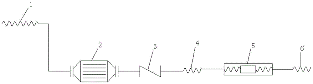
[0030] see figure 1 , a flameproof assembly for oil and gas recovery system, including hose I1, flame arrester 2, check valve 3, hose II4, breakaway valve 5 and hose III6, said hose I1, flame arrester 2, Check valve 3, hose II 4, breakaway valve 5 and hose III 6 are connected in sequence. The flameproof assembly of the present invention is arranged on the oil and gas output pipeline between any two adjacent oil storage tanks. When one of the oil storage tanks explodes due to special circumstances, the flameproof assembly can prevent other adjacent oil storage tanks from Cascading explosions occur in the tanks, thereby improving the safety of the oil vapor recovery system.

[0031] Further, the flame arrester 2 is a detonation-resistant flame arrester. The detonation-resistant flame arrester can be purchased on the market. The anti-detonation flame arrester can block the transmission of ignition energy during explosion.

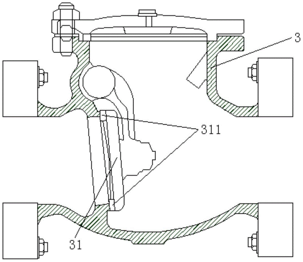
[0032] Further, see figure 2 , the check valve 3 m...

Embodiment 2

[0043] see Figure 5 , the present embodiment discloses an oil and gas recovery system, including several oil storage tanks 7, the explosion-proof assembly for the oil and gas recovery system in Embodiment 1, a flame arrester X9 and an oil and gas recovery device 10, each oil storage tank 7 Each is provided with a breather valve 8, and a three-way valve (not shown in the figure) is arranged between the oil storage tank 7 and the breather valve 8 on it, and each three-way valve is connected with a flameproof assembly, and the flameproof The assembly includes hose I1, flame arrester 2, check valve 3, hose II4, breakaway valve 5 and hose III6, said hose I1, flame arrester 2, check valve 3, hose II4, breakaway valve 5 and the hose III6 are connected in sequence, the hose I1 is connected to the three-way valve, each hose III5 is connected to the flame arrester X9, and the flame arrester X9 is connected to the oil vapor recovery device 10. A valve can be set between the flame arres...

Embodiment 3

[0047] This embodiment discloses an oil and gas recovery system, and the oil and gas recovery system includes the flameproof assembly used in the oil and gas recovery system in Embodiment 1.

[0048] The working process of the flameproof assembly is described below.

[0049] Assuming that the oil and gas in a certain oil storage tank explodes due to some special circumstances, the flame of the explosion is extinguished through the flame arrester 2, and the high pressure generated by the explosion enters the breakaway valve 5 through the check valve 3, and the breakaway valve 5 is under the action of pressure. Automatic disconnection, the pipeline stops working, and the check valve 3 is closed after stopping working, and the liquid in the pipeline no longer flows, which can prevent the flame from pouring back. At the same time, it also prevents the high pressure from being transmitted to other oil storage tanks, so as to protect other oil storage tanks.

[0050] When resuming ...


PUM


Abstract

The invention relates to an explosion-proof assembly, in particular to an explosion-proof assembly used for an oil-gas recycling system of oil storage tank headspace gas and the oil-gas recycling system. The explosion-proof assembly comprises one or more hoses I, one or more fire barriers, one or more check valves, one or more hoses II, one or more breaking valves and one or more hoses III which are connected with one another in sequence. Compared with the prior art, the explosion-proof assembly is arranged on an oil-gas output pipeline between any two adjacent oil storage tanks, when one of the oil storage tanks explodes due to special circumstances, the explosion-proof assembly can prevent chain explosion of other adjacent oil storage tanks from occurring, and the safety of the oil-gas recycling system is improved.

Description

technical field [0001] The invention relates to an explosion-proof assembly, in particular to an explosion-proof assembly and an oil-gas recovery system used in an oil storage tank roof gas oil recovery system. Background technique [0002] A breathing valve is generally installed on the normal pressure oil storage tank. When the temperature in the oil storage tank rises or the oil storage tank is filled with oil, the mixed oil and gas in the oil storage tank will be exhaled into the atmosphere through the breathing valve. This volatile combustible oil-gas mixture is exhaled into the atmosphere, which not only causes waste of oil storage, but also pollutes the environment. When this mixed oil and gas encounters an open flame or static electricity, it is easy to cause the oil storage to burn and the oil tank to explode. Since the oil and gas lost by evaporation are mainly the lighter components in the oil, the evaporation loss of the oil not only causes a loss in quantity, b...

Claims


Application Information

Patent Timeline
Patent Type & Authority Patents(China)
IPC IPC(8): B65D90/30F16K15/03F16K17/40
CPCB65D90/30
Inventor 白爽
Owner 上海森鑫新能源科技有限公司
Why Eureka
Try Eureka