An explosion-proof device for an industrial powder explosive production line

A production line and powder technology, which is applied to the field of explosion-proof devices for industrial powder explosive production lines, can solve problems such as explosion damage, casualties, and human body damage, and achieve the effects of reducing explosion power, preventing explosion and fire, and reducing damage.

Active Publication Date: 2021-09-03
重庆神斧锦泰化工有限公司
View PDF0 Cites 0 Cited by
  • Summary
  • Abstract
  • Description
  • Claims
  • Application Information

AI Technical Summary

Problems solved by technology

[0003] Generally, explosives need safe and reliable explosion-proof and explosion-proof devices during production. Nowadays, people's safety awareness is getting stronger and stronger. Traditional explosion-proof and explosion-proof devices can no longer meet people's requirements for safety protection strength. When explosives are produced and transported , conveyed through the conveying mechanism, and the finished explosives accumulate more, once an explosion occurs, it will cause very large damage, and may also cause casualties. The traditional explosion-proof device is simply to prevent explosion from the aspect of explosion venting. However, if the explosion shock wave cannot be completely vented, the machine will be exploded, and the splashed fragments will still damage the human body. Therefore, there is a need for a device that can reduce the probability of explosion and prevent the explosion from being completely vented. The blown-up machine damages the human body again. For this reason, the present invention proposes an explosion-proof device for an industrial powder explosive production line to solve the above problems

Method used


Image

  • An explosion-proof device for an industrial powder explosive production line
  • An explosion-proof device for an industrial powder explosive production line
  • An explosion-proof device for an industrial powder explosive production line

Examples


Embodiment Construction

[0017] The following will clearly and completely describe the technical solutions in the embodiments of the present invention with reference to the accompanying drawings in the embodiments of the present invention. Obviously, the described embodiments are only some, not all, embodiments of the present invention. Based on the embodiments of the present invention, all other embodiments obtained by persons of ordinary skill in the art without making creative efforts belong to the protection scope of the present invention.

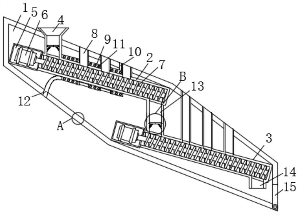
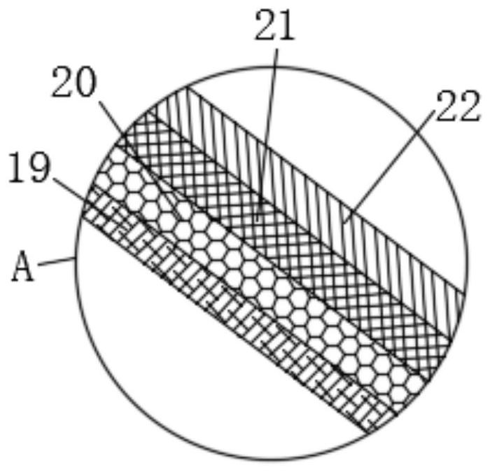
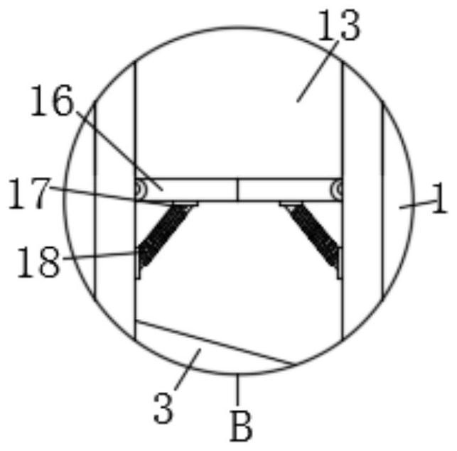
[0018] see Figure 1 to Figure 3 , the present invention provides a technical solution: an explosion-proof device for an industrial powder explosive production line, including an explosion-proof box 1, a cooling conveyor 2, a discharge conveyor 3 and a liquid cooler 9, and the explosion-proof box 1 is fixedly arranged on the cooling conveyor 2 and the outer side of the discharge conveyor 3, there is a through hole at the upper end of the explosion-proof box 1,...


PUM


Abstract

The invention provides an explosion-proof device for an industrial powder explosive production line, which includes an explosion-proof box, a cooling conveyor, a discharge conveyor and a liquid cooler. The explosion-proof box is fixed on the outside of the cooling conveyor and the discharge conveyor. There is a through hole at the upper end, and a material inlet is fixedly connected in the through hole. The lower end of the material inlet is connected to the cooling conveyor. The front end of the cooling conveyor is fixedly connected to a motor box, and a motor is fixedly connected to the motor box. The transmission output of the motor The end is fixedly connected with a screw conveying rod, and the outer side of the screw conveying rod is fixedly connected with a spiral conveying leaf. The invention has the function of explosion-proof and explosion-proof, and can effectively prevent machine fragments from splashing and damaging the human body when the explosion-proof machine cannot be fully vented. It can effectively buffer the impact of the explosion and prevent the explosion from igniting, and when one of the sections explodes, the explosion range can be controlled within this section to prevent the explosion from causing chain explosions.

Description

technical field [0001] The invention relates to the technical field of explosion-proof devices, in particular to an explosion-proof device for an industrial powder explosive production line. Background technique [0002] Explosive material is a substance that can burn violently (that is, explode) in a very short time. It is a substance that explodes by its own energy under the action of a certain amount of external energy. Under normal circumstances, the chemical and physical properties of explosives are stable, but regardless of whether the environment is sealed or not, the amount of charge, or even in the case of zero oxygen supply from the outside world, as long as there is strong energy (provided by the detonator) to stimulate, the explosives will be released to the outside world. Carry out stable detonation type work. When the explosive explodes, it can release a large amount of heat energy and generate high-temperature and high-pressure gas, which can damage, throw, a...

Claims


Application Information

Patent Timeline
Patent Type & Authority Patents(China)
IPC IPC(8): C06B21/00
CPCC06B21/00
Inventor 罗国文龙玉喜唐封林赵杰邱文杨
Owner 重庆神斧锦泰化工有限公司
Why Eureka
Try Eureka