Cell delivery mechanism

A technology of conveying mechanism and battery cell, applied in conveyors, mechanical conveyors, secondary battery manufacturing, etc., can solve the problem of low efficiency and so on

Inactive Publication Date: 2015-07-22
SHENZHEN YINGHE TECH
View PDF7 Cites 9 Cited by
  • Summary
  • Abstract
  • Description
  • Claims
  • Application Information

AI Technical Summary

Problems solved by technology

These processes are all carried out individually, and the efficiency is not high

Method used


Image

  • Cell delivery mechanism
  • Cell delivery mechanism
  • Cell delivery mechanism

Examples


Embodiment Construction

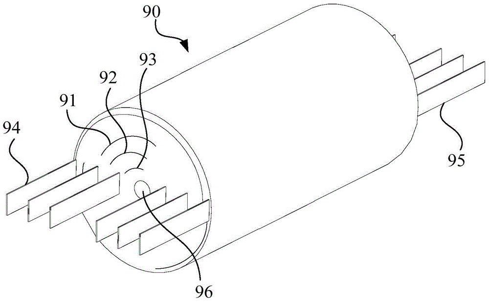
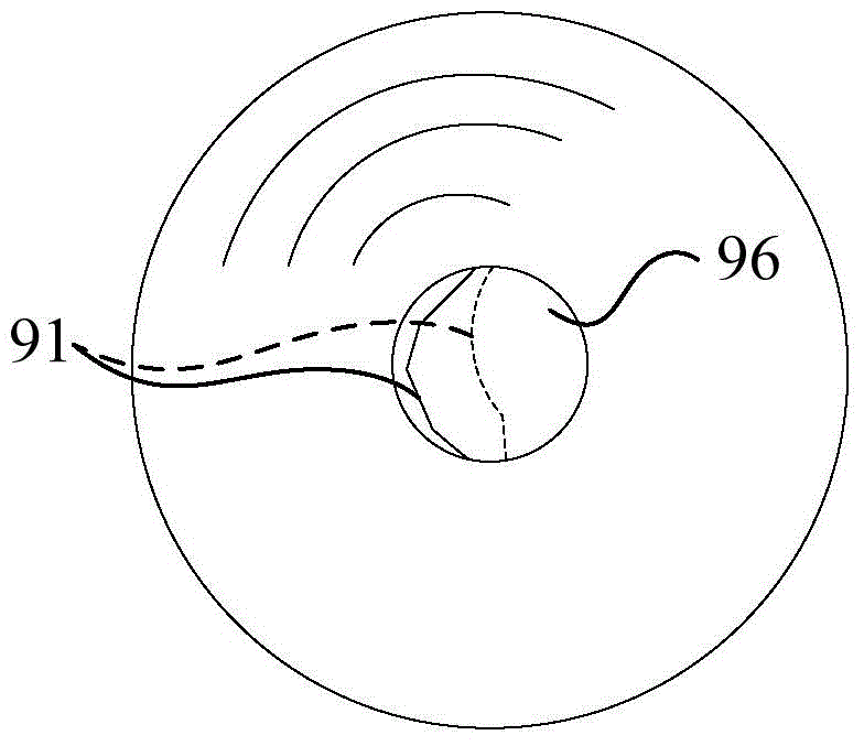
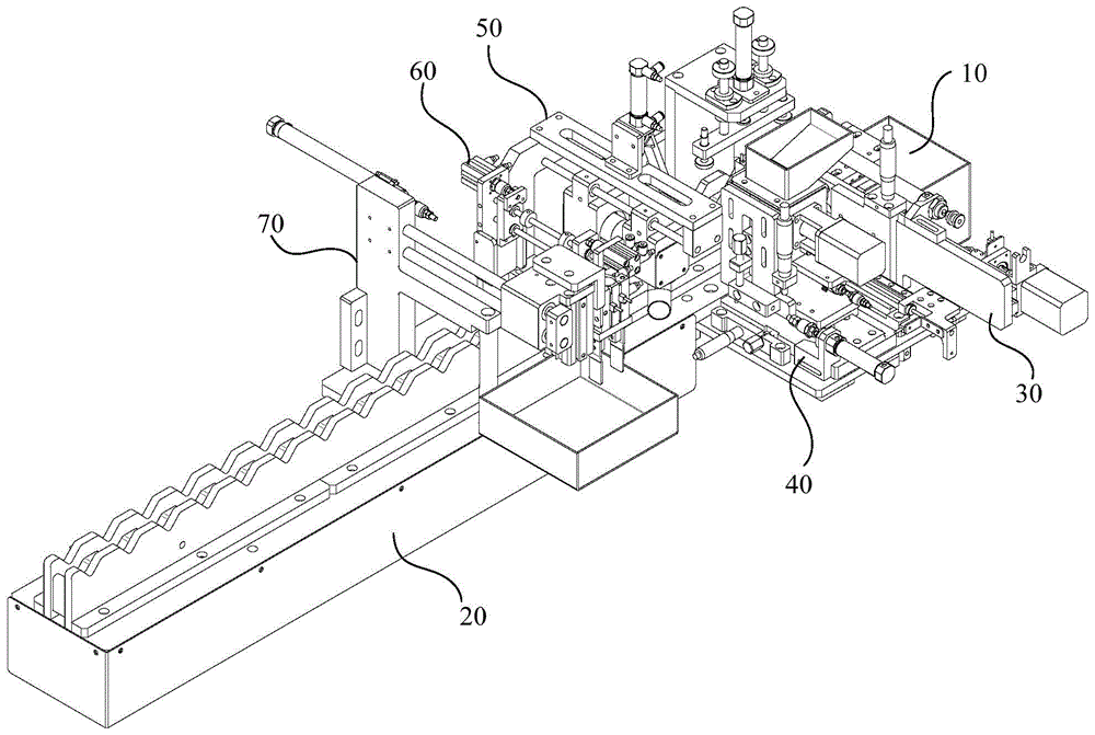
[0025] Such as image 3 and Figure 4 As shown, the cell processing device provided by an embodiment includes a screening mechanism 10 , a transmission mechanism 20 , a hole expansion mechanism 30 , a pipe threading mechanism 40 , a dust removal mechanism 50 , a short circuit test mechanism 60 and a defective product removal mechanism 70 . The screening mechanism 10 is arranged at the upstream end of the conveying mechanism 20 , and preliminarily screens the battery cells 90 to be processed. The screened battery cells 90 are placed on the conveying mechanism 20 and conveyed downstream by the conveying mechanism 20 . The hole reaming mechanism 30, the pipe threading mechanism 40, the dust removal mechanism 50, the short circuit testing mechanism 60 and the defective product rejecting mechanism 70 are arranged on the conveying path of the conveying mechanism 20 in sequence from upstream to downstream, wherein the reaming mechanism 30 is used for The shaft hole 96 of the electri...


PUM


Abstract

The invention relates to a cell delivery mechanism which is used for delivering cells of batteries for subsequent processing on an assembly line. The cell delivery mechanism comprises a first delivery frame, a second delivery frame, a first power source and a second power source, wherein processing stations used for bearing the cells are arranged on the first delivery frame and the second delivery frame, the first power source is connected with the second delivery frame and is used for driving the second delivery frame opposite to the first delivery frame in the direction parallel with the delivery plane of the cells, and the second power source is connected with the second delivery frame and is used for driving the second delivery frame opposite to the first delivery frame in the direction perpendicular to the delivery plane of the cells. The corresponding processing stations are arranged on the first delivery frame and the second delivery frame, the second delivery frame moves opposite to the first delivery frame in two different directions, and therefore the cells are moved to next adjacent processing stations of the downstream in sequence. The cell delivery mechanism is accurate in delivery positioning, facilitates automatic processing of the wound cells, and is simple in delivery structure and easy to achieve.

Description

technical field [0001] The invention relates to the field of battery electric cores, in particular to an electric core transmission mechanism for performing post-processing on wound initially formed electric cores. Background technique [0002] An existing manufacturing method for electric cores is to wind the positive and negative pole pieces, separators, and positive and negative tabs with the reel of the winding machine to have the following characteristics: figure 1 The electric core 90 of the structure shown in. The reel of the winding machine is divided into two pieces, and placed on the front and back sides of the diaphragm 91, and the diaphragm 91, positive and negative electrode sheets 92, 93 are wound together by rolling the reel. The separator 91 electrically isolates the rolled positive and negative electrode sheets 92 and 93 , and the positive and negative electrode lugs 94 and 95 are respectively electrically connected to the positive and negative electrode sh...

Claims


Application Information

Patent Timeline
Patent Type & Authority Applications(China)
IPC IPC(8): B65G35/00H01M10/04
CPCY02E60/10Y02P70/50
Inventor 张勇罗选良何爱彬
Owner SHENZHEN YINGHE TECH
Why Eureka
Try Eureka