

Lifting trolley
Patent Information
- Authority / Receiving Office
- CN · China
- Patent Type
- Patents(China)
- Current Assignee / Owner
- ZHANGSHU ZHISHENG FORGING
- Publication Date
- 2017-03-08
Smart Images
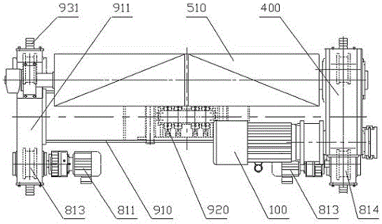
Figure 1 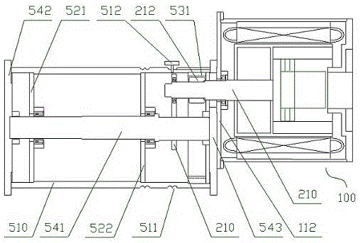
Figure 2 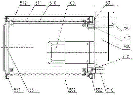
Figure 3
Abstract
Description
technical field
[0001] The invention relates to a lifting trolley suitable for bridge cranes and other equipment. Background technique
[0002] The lifting trolley is usually composed of a frame, a lifting mechanism and a walking mechanism installed on the frame. The main function of the lifting mechanism is to wind or release the wire rope through the reel, and place the object connected to the end of the wire rope at a certain height. , the driving device of the reel usually uses an AC asynchronous motor as the prime mover, and is connected with the reel drive through a corresponding reduction device, so as to convert the high speed of the AC asynchronous motor into the low speed required for the work of the reel, and the traveling mechanism includes A number of road wheels installed on the front and rear end beams of the frame respectively to support and drive the lifting trolley to move horizontally. The road wheels usually include driving wheels and driven wheels, where...