Reciprocating piston built-in chained connecting rod dead-point-free engine piston connecting rod set

A technology of reciprocating pistons and piston connecting rods, which is applied to engine components, machines/engines, pistons, etc., can solve the problems of easy wear, waste of resources, and dead spots at the joints between pistons and connecting rods, and achieve the elimination of engine dead spots, The effect of avoiding waste and reducing loss

Inactive Publication Date: 2015-07-22
尹建
View PDF6 Cites 1 Cited by
  • Summary
  • Abstract
  • Description
  • Claims
  • Application Information

AI Technical Summary

Problems solved by technology

But there is following deficiency in existing piston connecting rod group: 1, when piston moves to top dead center and bottom dead center, all can occur dead point, and existing engine all can't thoroughly solve the problem of engine dead point
2. The connection between the piston and the connecting rod is easy to wear and tear. After the damage, the piston cannot continue to be used. Only the piston can be replaced, and the piston is only worn at the connection with the connecting rod. Therefore, replacing the piston will cause waste of resources and high cost

Method used


Image

  • Reciprocating piston built-in chained connecting rod dead-point-free engine piston connecting rod set
  • Reciprocating piston built-in chained connecting rod dead-point-free engine piston connecting rod set
  • Reciprocating piston built-in chained connecting rod dead-point-free engine piston connecting rod set

Examples


Embodiment Construction

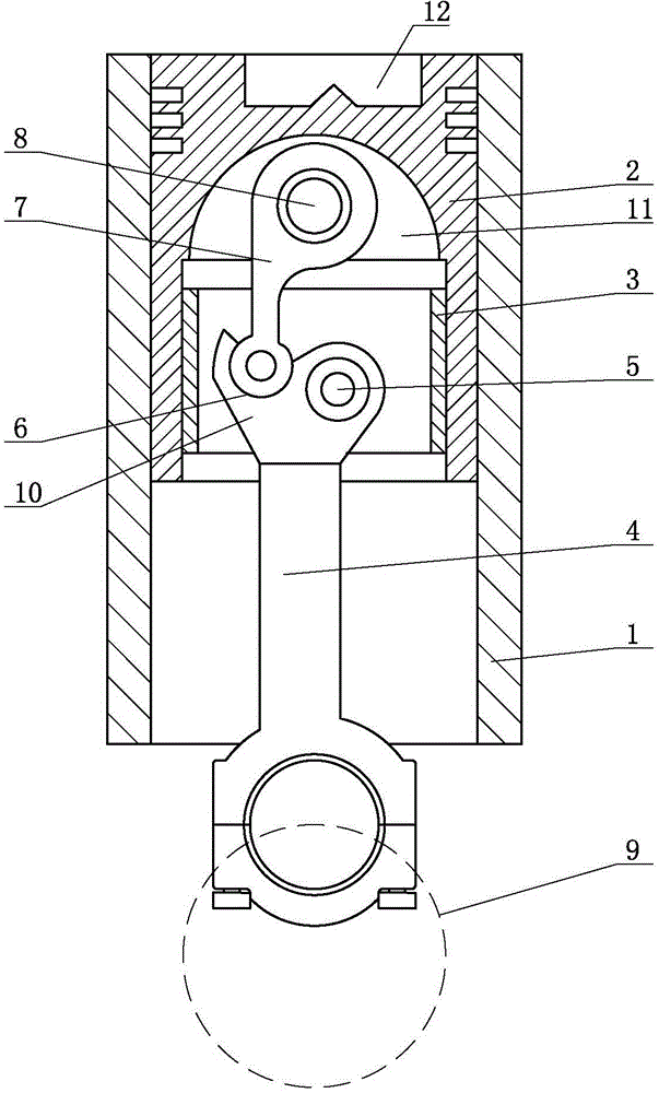
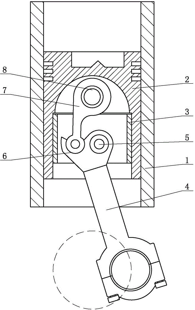
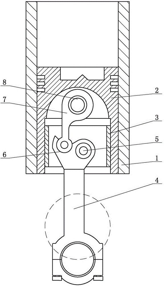
[0009] The reciprocating piston built-in chain-type connecting rod of the present invention has no dead point engine piston connecting rod group, such as figure 1 As shown, the connecting rod 4 and the piston 2 are included, and the bottom of the piston 2 is hollow. A movable sleeve 3 is arranged in the inner cavity 11 at the bottom of the piston 2 , and the movable sleeve 3 can move axially along the inner wall of the inner cavity 11 . The piston 2 provides guidance for the movable sleeve 3 so that the movable sleeve 3 can reciprocate along the axis of the inner cavity 11 . A first fixed shaft 5 is arranged in the movable sleeve 3, and the small head of the hinged connecting rod 4 is connected on the first fixed shaft 5. One side of the small head of connecting rod 4 is provided with shifting block 10. Offer groove or pin hole 6 on shifting block 10, groove or pin hole 6 are positioned at first fixed shaft 5 one side, one end of push rod 7 is arranged in groove or pin ...


PUM


Abstract

The invention discloses a reciprocating piston built-in chained connecting rod dead-point-free engine piston connecting rod set. The reciprocating piston built-in chained connecting rod dead-point-free engine piston connecting rod set comprises a piston and a connecting rod. The bottom of the piston is hollow, a movable sleeve is arranged in an inner cavity in the bottom of the piston and can axially move along the inner wall of the inner cavity, the movable sleeve is internally provided with a first fixing shaft, the small end of the connecting rod is hinged to the first fixing shaft, a stirring block is arranged at the side of the small end of the connecting rod, a groove or a pin hole is formed in the stirring block and located in one side of the first fixing shaft, one end of a push rod is arranged in the groove or the pin hole in a matched mode, the other end of the push rod is hinged to a second fixing shaft, and the second fixing shaft is installed in the inner cavity of the piston. The movable sleeve can do reciprocating movement in the inner cavity along the axis, and the piston guides for the movable sleeve. According to the reciprocating piston built-in chained connecting rod dead-point-free engine piston connecting rod set, the dead point of an engine can be fundamentally eliminated, energy consumption is reduced, and the loss of the piston connecting rod set and a crankshaft is reduced. Replacing is facilitated after abrasion, waste is avoided, heat dissipating is more convenient, strength is higher, and the running efficiency of the engine can be effectively ensured.

Description

technical field [0001] The invention relates to an engine piston and connecting rod group, in particular to a reciprocating piston built-in chain connecting rod and no dead point engine piston and connecting rod group. Background technique [0002] In the current engine piston and connecting rod group, the piston moves up and down to push the connecting rod to swing and reciprocates up and down, thereby driving the crankshaft to rotate. But there is following deficiency in existing piston connecting rod group: 1, when piston moves to top dead center and bottom dead center, all can occur dead point, and existing engine all can't thoroughly solve the problem of engine dead point. 2. The connection between the piston and the connecting rod is easy to wear and tear. After the damage, the piston cannot continue to be used, and the piston can only be replaced, and the piston only wears out at the connection with the connecting rod. Therefore, replacing the piston will cause waste...

Claims


Application Information

Patent Timeline
IPC IPC(8): F16J1/16F02F3/00
CPCF02F3/00F16J1/16F02B75/32F02F3/0015
Inventor 尹建
Owner 尹建
Why Eureka
Try Eureka