Support device for portable projection device

A technology of projection equipment and bracket device, which is applied in the direction of mechanical equipment, machine platform/bracket, supporting machine, etc., which can solve the problems of inconvenient operation, difficulty in guaranteeing projection effect, easy recovery, etc., and achieves convenient portability and storage, and great promotion and application value , Quick installation and adjustment effect

Active Publication Date: 2015-07-22
CHANGSHA GUANCHUANG CONTROL TECH CO LTD
View PDF6 Cites 2 Cited by
  • Summary
  • Abstract
  • Description
  • Claims
  • Application Information

AI Technical Summary

Problems solved by technology

After the projector is installed, the position remains basically unchanged, which completely fails to meet the requirements of portable projection equipment that is ready to install, use and disassemble
For example, it cannot meet the requirements of quick and easy use of a projector in multiple rooms in a home
[0006] Some practitioners have proposed a miniature projector bracket composed of a fixed base that can clamp the back plate, a bendable metal tube, a universal head, and a projector base. very troublesome
In particular, the hardness of its bendable metal tube is difficult to control. If it is too hard, it is inconvenient for users to operate, and it is easy to recover after bending. If it is too soft, it is easy to deform, and the projection effect is difficult to guarantee.
[0007] Another practitioner has proposed a Z-shaped folding tabletop projector bracket, which can be easily moved, and can also be folded and lifted arbitrarily. Theoretically, the projection effect can be guaranteed, but it must have a fixed plane similar to a desktop or coffee table, and Portable projectors cannot guarantee this in many occasions
For example: the central position of the family bedroom is often a bed, which cannot provide a fixed surface

Method used


Image

  • Support device for portable projection device
  • Support device for portable projection device
  • Support device for portable projection device

Examples


Embodiment Construction

[0028] The present invention will be further described in detail below in conjunction with the accompanying drawings and specific embodiments.

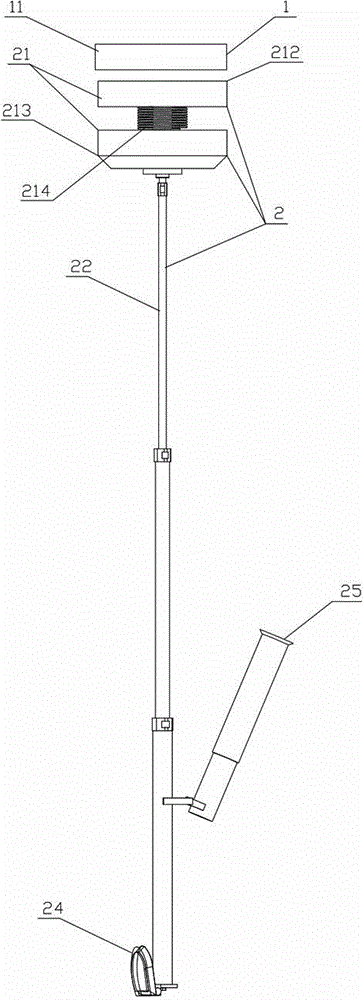
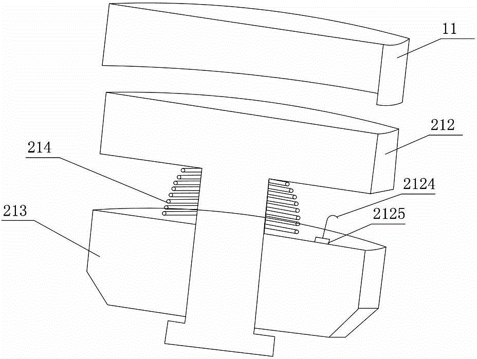
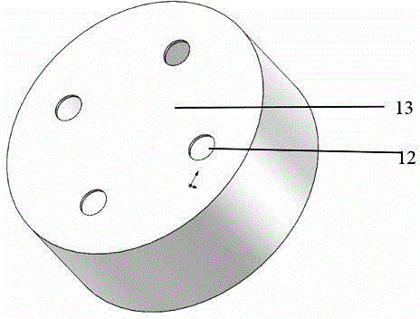
[0029] like Figure 1 to Figure 6 As shown, a bracket device for portable projection equipment of the present invention includes a fixed assembly 1 and a movable assembly 2, the fixed assembly 1 includes a fixed plate 11, the fixed plate 11 is used to install and fix on a fixed surface, and the fixed plate 11 has a cavity for socketing the movable assembly 2; the movable assembly 2 includes a connection plate 21 and a telescopic rod mechanism 22, the connection disk 21 and the fixed disk 11 realize docking or separation through cooperation, and one end of the telescopic rod mechanism 22 is connected to On the connecting plate 21 , the other end is provided with a projector installation surface 24 , and the portable projection device is installed on the projector installation surface 24 .

[0030] In this embodiment, the fixed disk 11...


PUM


Abstract

The invention discloses a support device for a portable projection device. The support device comprises a fixed assembly and a movable assembly. The fixed assembly comprises a fixing disc, the fixing disc is used for being installed on and fixed to a fixing face, and the fixing disc is provided with a cavity, wherein the movable assembly is sleeved with the cavity. The movable assembly comprises a connecting disc and a telescopic rod mechanism, the connecting disc and the fixing disc are matched to be connected in a butt joint mode or separated, one end of the telescopic rod mechanism is connected to the connecting disc, the other end of the telescopic rod mechanism is provided with a projector installation face, and the portable projection device is installed on the projector installation face. The support device has the advantages of being simple and compact in structure, low in cost, convenient to quickly install and adjust and the like.

Description

technical field [0001] The invention mainly relates to the field of projection equipment, in particular to a bracket device mainly suitable for portable projection equipment and miniature projection equipment. Background technique [0002] With the continuous application and development of various projection technologies such as LCOS, DLP and even laser, various miniaturized and micro-projector products continue to emerge, which greatly improves the portability of projection equipment. Portable projectors are not only used in various office spaces, but also have begun to enter thousands of households. [0003] Portable projectors are extremely rich in product types, some of which are only the size of a palm and weigh only 0.5kg. Their projection effect has surpassed that of common high-definition TVs, and their volume and energy consumption are far lower than that of TVs, and their cost performance is much higher than that of TVs. . In particular, most of the current micro...

Claims


Application Information

Patent Timeline
Patent Type & Authority Applications(China)
IPC IPC(8): F16M13/02F16M11/12F16M11/18G03B17/56
Inventor 曾逸凡
Owner CHANGSHA GUANCHUANG CONTROL TECH CO LTD
Why Eureka
Try Eureka