Establishing method of LED filament lamp and LED filament lamp

A technology for LED filament lamps and LED filaments, which is applied to the layout of electric lamp circuits, components of lighting devices, semiconductor devices of light-emitting elements, etc. Difficulties and other issues, to reduce the difficulty of assembly, improve conversion efficiency and power factor, and reduce production costs

Active Publication Date: 2015-07-22
GUIZHOU GUANGPUSEN PHOTOELECTRIC
View PDF7 Cites 18 Cited by
  • Summary
  • Abstract
  • Description
  • Claims
  • Application Information

AI Technical Summary

Problems solved by technology

[0003] It is the best solution for general lighting to supply LED filament lamps directly with the mains power supply. If the LED filament is powered by converting the AC mains voltage into a DC constant current output, it will inevitably lead to a large volume and high cost of the driving power supply. , when constructing LED filament lamps, there are difficulties in the arrangement of the power supply
Moreover, in order to meet the requirements of different mains voltage levels for LED filament lamps in the world, a variety of LED filaments with different typical forward voltage levels are required to match, which further increases the difficulty of building LED filament lamps, and also requires the types of LED filaments. Higher requirements are put forward, which reduces the versatility and interchangeability of LED filaments in lamps of various voltage levels

Method used


Image

  • Establishing method of LED filament lamp and LED filament lamp
  • Establishing method of LED filament lamp and LED filament lamp
  • Establishing method of LED filament lamp and LED filament lamp

Examples


Embodiment Construction

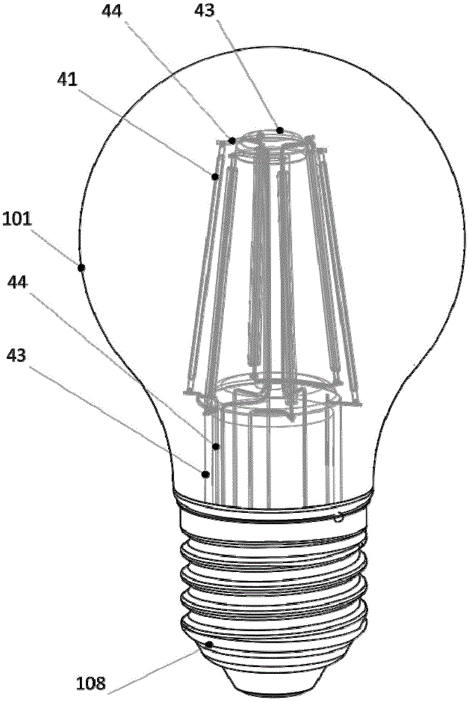
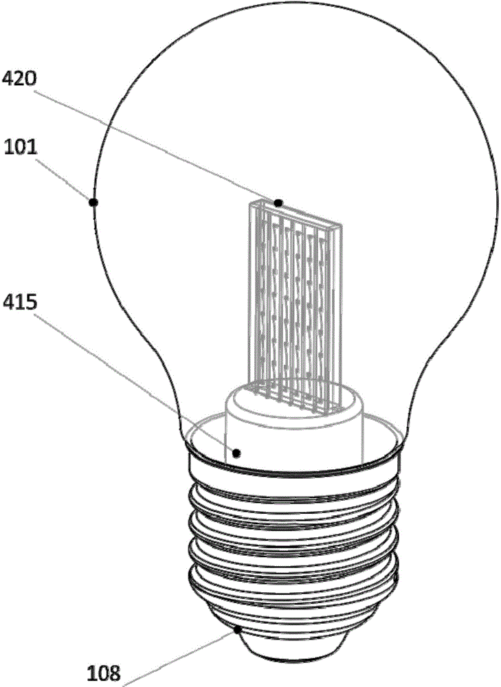
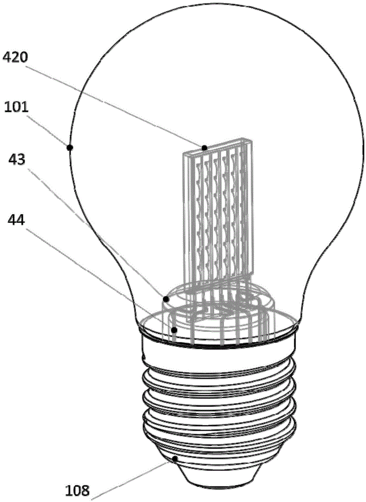
[0043] The present invention will be further described below in conjunction with the accompanying drawings and embodiments, but not as a basis for limiting the present invention.

[0044] Example. A method for constructing an LED filament lamp: a bulb shell and a lamp cap are arranged outside the LED light source core component, and wires are arranged to connect the LED light source core component with the lamp cap to form an LED filament lamp; the LED light source core component consists of an LED filament group, a built-in LED drive power supply module and binding posts; the LED filament group is composed of multiple LED series groups connected in series; the LED series group is packaged in series on a strip-shaped substrate by multiple LED chips or LED PN junctions to form an LED The filament, or the plurality of LED series groups are all packaged in series on the same substrate to form a combined LED filament; the two ends of the LED filament group are connected to the fix...


PUM


Abstract

The invention discloses an establishing method of an LED filament lamp and the LED filament lamp. A lamp bulb shell and a lamp cap are arranged outside an LED light source core assembly, the LED light source core assembly is connected with the lamp cap through a wire, and then the LED filament lamp is formed. The LED light source core assembly is composed of an LED filament set, a built-in LED drive power supply module and wiring columns. The two ends of the LED filament set are connected to the fixed welding points of the built-in LED drive power supply module through the wiring columns playing a supporting role; or, the serial-connection points of the LED filament set are also connected to the fixed welding points of the built-in LED drive power supply module through the wiring columns playing the supporting rod. The establishing complexity of the LED filament lamp can be reduced. When LED filament lamps of different typical forward voltage grade requirements are established through non-voltage-reduction rectifying power supply under different mains supply voltage grades, an LED filament can have higher universality and interchangeability.

Description

technical field [0001] The invention relates to a construction method of an LED filament lamp and an LED filament lamp, belonging to the technical field of LED lighting. Background technique [0002] In the past, to achieve a certain illuminance and illumination area for LED light sources, it was necessary to install optical devices such as reflective surfaces and lenses, which affected the lighting effect and reduced the energy-saving effect of LEDs. Multiple LED chips or LED PN junctions are packaged on a strip-shaped substrate in the form of an LED series group, preferably a transparent strip-shaped substrate, to form an LED filament. The LED filament can emit light at all angles of 360°. It emits light at a large angle without adding a lens, realizing a three-dimensional light source and bringing an unprecedented lighting experience. [0003] It is the best solution for general lighting to supply LED filament lamps directly with the mains power supply. If the LED filame...

Claims


Application Information

Patent Timeline
Patent Type & Authority Applications(China)
IPC IPC(8): F21S2/00F21V19/00F21V23/00H05B37/02F21Y101/02F21K9/232F21Y107/00F21Y115/10
CPCF21V19/002F21V23/003H05B47/10F21S2/00
Inventor 张继强张哲源
Owner GUIZHOU GUANGPUSEN PHOTOELECTRIC
Why Eureka
Try Eureka