LED (Light-Emitting Diode) light source drilling-free rapid fixing structure

A technology of LED light source and fixed structure, applied in the direction of light source fixation, light source, electric light source, etc., can solve the problems of mismatch between drilling and screw holes, complicated installation, inability to install, etc., to achieve convenient splicing and position adjustment, and improve tolerance Fault tolerance, the effect of reducing installation difficulty

Active Publication Date: 2015-07-22
GUANGZHOU LUMBENCY LIGHTING
View PDF8 Cites 0 Cited by
  • Summary
  • Abstract
  • Description
  • Claims
  • Application Information

AI Technical Summary

Problems solved by technology

[0003] 1. Due to the tolerance and the material difference between the shell and the circuit board, the matching drilling and screw holes in the design are prone to mismatch when the finished product is assembled, resulting in inaccurate or impossible installation problems;
[0004] 2. When installing the long strip housing and the LED substrate, it is necessary to use more screws along the extension path for fixing, and the installation is more cumbersome;
[0005] 3. Since the drilling and screw holes need to be determined in advance, when multiple LED substrates are used for splicing on a long housing, it will cause the problem that the drilling and screw holes do not match, and it cannot be installed. Therefore, the housing and the drive power and Poor adaptability of LED substrate matching;
[0006] 4. The position of the drive power supply and the LED substrate on the housing can only be installed according to the positions of the existing drilling and screw holes, and the relative positions of the housing, the drive power supply and the LED substrate cannot be adjusted arbitrarily

Method used


Image

  • LED (Light-Emitting Diode) light source drilling-free rapid fixing structure
  • LED (Light-Emitting Diode) light source drilling-free rapid fixing structure

Examples


Embodiment Construction

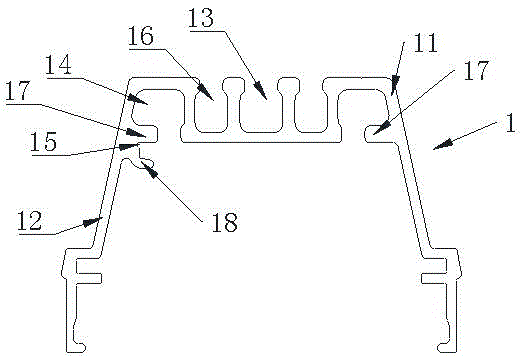
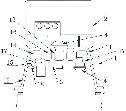
[0022] Such as figure 1 As shown, the fast fixing structure of the LED light source without drilling in this embodiment includes a housing 1, a driving power supply 2 is provided on the back of the housing 1, and an LED substrate 3 is provided inside the housing 1. The housing 1 It includes a component mounting part 11 and side shell parts 12 extending obliquely downward from both sides of the component mounting part 11. The component mounting part 11 and the side shell parts 12 extend in a strip shape. The surface is provided with one or more driving power fixing grooves 13 inwardly recessed, and the driving power fixing grooves 13 extend along the extension direction of the component mounting part 11, and the driving power 2 is fixed to the driving power fixing grooves 13 by fasteners 4 Middle; the lower surface of the component mounting part 11 is provided with an LED substrate fixing groove 14, and a card slot 15 is provided on the inner wall of the side shell part 12 on ...


PUM


Abstract

The invention relates to an LED (Light-Emitting Diode) light source installing structure, in particular to an LED light source drilling-free rapid fixing structure. The structure comprises a shell, wherein the back of the shell is provided with a driving power supply, the shell is internally provided with an LED base plate, and the shell comprises a component mounting part and side shell parts; the side shell parts extend downwards from two side of the component mounting part, the upper surface of the component mounting part is provided with one or more driving power supply fixing grooves which are concave inwards, and the driving power is fixedly arranged in the driving power fixing groove by virtue of a fastening piece; the lower surface of the component mounting part is provided with an LED base plate fixing groove, and the inner wall of the side shell part on one side is provided with a clamping slot. The tolerance fault tolerance is greatly improved by virtue of the LED light source drilling-free rapid fixing structure, the LED base plate is matched with the clamping slot by virtue of the single fastening piece, so as to realize fixing; the mounting difficulty is lowered, the cross-ventilation is convenient, the better heat dissipation is realized, the fastening piece can be arbitrarily selected and arranged in the mounting groove, so that the LED light source drilling-free rapid fixing structure is capable of providing convenience for splicing and position adjusting of the LED base plate.

Description

technical field [0001] The invention relates to an LED light source installation structure, in particular to a drilling-free fast fixing structure for an LED light source. Background technique [0002] The use of LED lighting equipment is becoming more and more widespread, replacing traditional light sources in many products, such as alternative lamp tubes or other strip-shaped light sources. There are two mounting planes, the upper mounting plane is used for installing the drive power supply, and the lower mounting plane is used for installing the LED substrate. When the existing casing is installed with the drive power supply and the LED substrate, it is generally first to drill holes on the upper installation plane and the lower installation plane respectively, and preset screw holes when processing the drive power supply and the LED substrate, and then screw the drive power supply respectively. and the LED substrate are fixed on the upper installation plane and the lowe...

Claims


Application Information

Patent Timeline
Patent Type & Authority Applications(China)
IPC IPC(8): F21S9/00F21V19/00F21V17/10F21Y101/02F21Y115/10
CPCF21S9/00F21V17/10F21V19/0015F21V23/023
Inventor 吴淑汉
Owner GUANGZHOU LUMBENCY LIGHTING
Why Eureka
Try Eureka