Sealing gasket used in plate heat exchanger

A technology for plate heat exchangers and sealing gaskets, applied in heat exchanger sealing devices, indirect heat exchangers, heat exchanger types, etc., can solve the problems of small flow rates, low flow rates, low heat transfer coefficients, and inconvenient maintenance , to save installation and maintenance costs, improve heat transfer coefficient, and prove the effect of accuracy

Inactive Publication Date: 2015-07-22
SHANDONG UNIV
View PDF5 Cites 7 Cited by
  • Summary
  • Abstract
  • Description
  • Claims
  • Application Information

AI Technical Summary

Problems solved by technology

However, if two fluids with a large difference in flow rate are used for heat exchange, if the two fluids adopt parallel fluid channels, the flow rate of the smaller flow rate will be too low, resulting in a lower heat transfer coefficient
Therefore, the low-flow fluid channels are usually arranged in series, such as Figure 2a As shown, in this way, all four inlets and outlets of the hot and cold fluids cannot be set on one end plate, but can only be set on two end plates 5, 6, as Figure 2b As shown, the fluid inlet and outlet ports are set on both end plates. When the heat exchanger is connected to the pipeline, it will be difficult to disassemble the plate heat exchanger, and both ends need to be disassembled, resulting in inconvenient maintenance.

Method used


Image

  • Sealing gasket used in plate heat exchanger
  • Sealing gasket used in plate heat exchanger
  • Sealing gasket used in plate heat exchanger

Examples


Embodiment Construction

[0031] The specific embodiments of the present invention will be described in detail below in conjunction with the accompanying drawings.

[0032] In this article, if there is no special explanation, when it comes to formulas, " / " means division, and "×" and "*" mean multiplication.

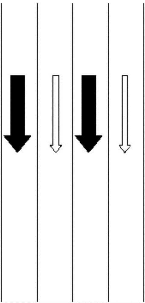
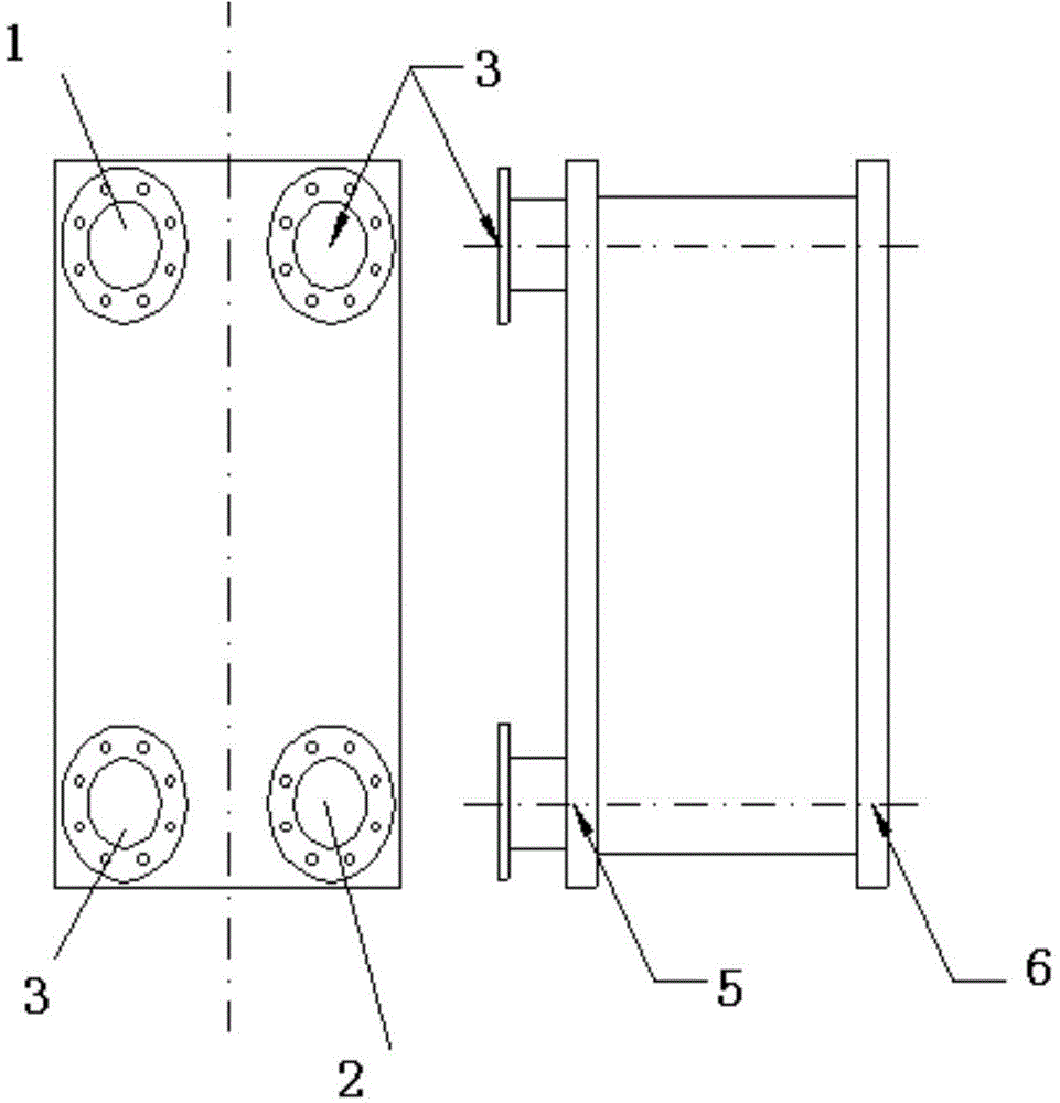
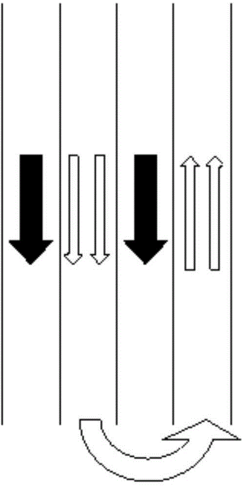
[0033] A heat exchange plate 10 used in a plate heat exchanger, wherein at least one flow splitting component is arranged in the heat exchange plate 10, and the flow path of the heat exchange fluid flowing through the heat exchange plate is divided into at least two There are three sub-pass flow channels 7, and the sub-pass flow channels 7 in the heat exchange plates 10 are in series structure. Through the series structure of the above-mentioned sub-range flow channels 7, the fluid passes through all the sub-range flow channels 7, such as Figure 6 As shown, the heat exchange fluid forms an S-shaped flow channel on the heat exchange plate 10 .

[0034] By setting the diversion parts, the fluid ...


PUM


Abstract

The invention provides a sealing gasket used in a plate heat exchanger. At least one flow dividing sealing pad is arranged in the sealing gasket. The flow dividing sealing pad divides the flowing path of heat exchanging fluid flowing through a heat exchanging plate sheet into at least two split-ranging flow ways. The sealing gasket is provided with an opening, so that the split-ranging flow ways in the heat exchanging plate sheet is of a serial-connecting structure, and accordingly the heat exchanging fluid forms an S-shaped flow way on the heat exchanging plate sheet. The requirements that cold and hot side fluid circulating sectional areas are not equal are met through the sealing gasket, a large amount of mounting and maintaining cost can be saved, meanwhile, heat exchanging efficiency is high, and the purposes of energy saving and environment protecting are achieved.

Description

technical field [0001] The invention belongs to the field of heat exchangers, in particular to a plate heat exchanger, which belongs to the field of F28D heat exchangers. Background technique [0002] In general, the cross-sectional areas of the cold and hot fluid passages on both sides of the plate heat exchanger are equal ( Figure 1a ). In this case, if the flow rate (referring to the volume flow rate) of the two fluids is not much different, the flow channels of the same fluid can be connected in parallel with each other, such as Figure 1a , at this time, the heat transfer coefficient of the fluids on both sides of the plate heat exchanger is not much different, and the heat transfer coefficient of the whole heat exchanger is very high, and this setting can also make the inlet and outlet of the two fluids on the same end plate 5, as shown in Figure 1b As shown, it is conducive to the disassembly and maintenance of the plate heat exchanger and the cleaning of the plates...

Claims


Application Information

Patent Timeline
Patent Type & Authority Applications(China)
IPC IPC(8): F28F11/02C08L7/00C08L23/16C08L9/06C08L83/04C08K13/02C08K3/22C08K3/36C08K3/34C08K5/3492
CPCF28D9/00F28F3/00F28F3/083F28F3/10F28F9/22F28F11/00Y02P20/10
Inventor 师艳平张冠敏田茂诚冷学礼范明秀
Owner SHANDONG UNIV
Why Eureka
Try Eureka