Circulation pump, heating system and method of determining the flow rate of a liquid through a pipe

a flow rate and flow technology, applied in the field of circular pumps, to achieve the effect of reducing installation costs, reducing the number of components, and increasing the operational reliability of the corresponding installation

Inactive Publication Date: 2009-05-14
ITT MFG ENTERPRISES LLC
View PDF12 Cites 18 Cited by
  • Summary
  • Abstract
  • Description
  • Claims
  • Application Information

AI Technical Summary

Benefits of technology

[0043]It is advantageous if the flow rate signal and / or flow rate switching signal is supplied to a control device of a heater, which is disposed at the pipe. This makes it easy to carry out flow rate monitoring, wherein no additional sensor or switch need be provided. The corresponding installation outlay is therefore reduced. What is more, the operational reliability of the corresponding installation is increased because the number of components is minimized.
[0044]It may be provided that the circulation pump supplies a flow rate-dependent switching signal with a defined hysteresis. The hysteresis defines at which flow rate the switching signal is “on” and at which flow rate the switching signal is “off” in dependence upon whether the flow rate has increased or has decreased. Such a switching signal may be used directly without further processing for control of a heater. By defining a corresponding hysteresis it is possible, particularly in a range of a limit flow, to prevent frequent switching of the heater, i.e. prevent a “fluttering” of the heater with regard to switching on and off. It is therefore possible to extend the service life of the corresponding system.

Problems solved by technology

If the flow rate of the liquid through the flow-through section is no longer adequate, then the heater has to be switched off.

Method used


Image

  • Circulation pump, heating system and method of determining the flow rate of a liquid through a pipe
  • Circulation pump, heating system and method of determining the flow rate of a liquid through a pipe
  • Circulation pump, heating system and method of determining the flow rate of a liquid through a pipe

Examples


Embodiment Construction

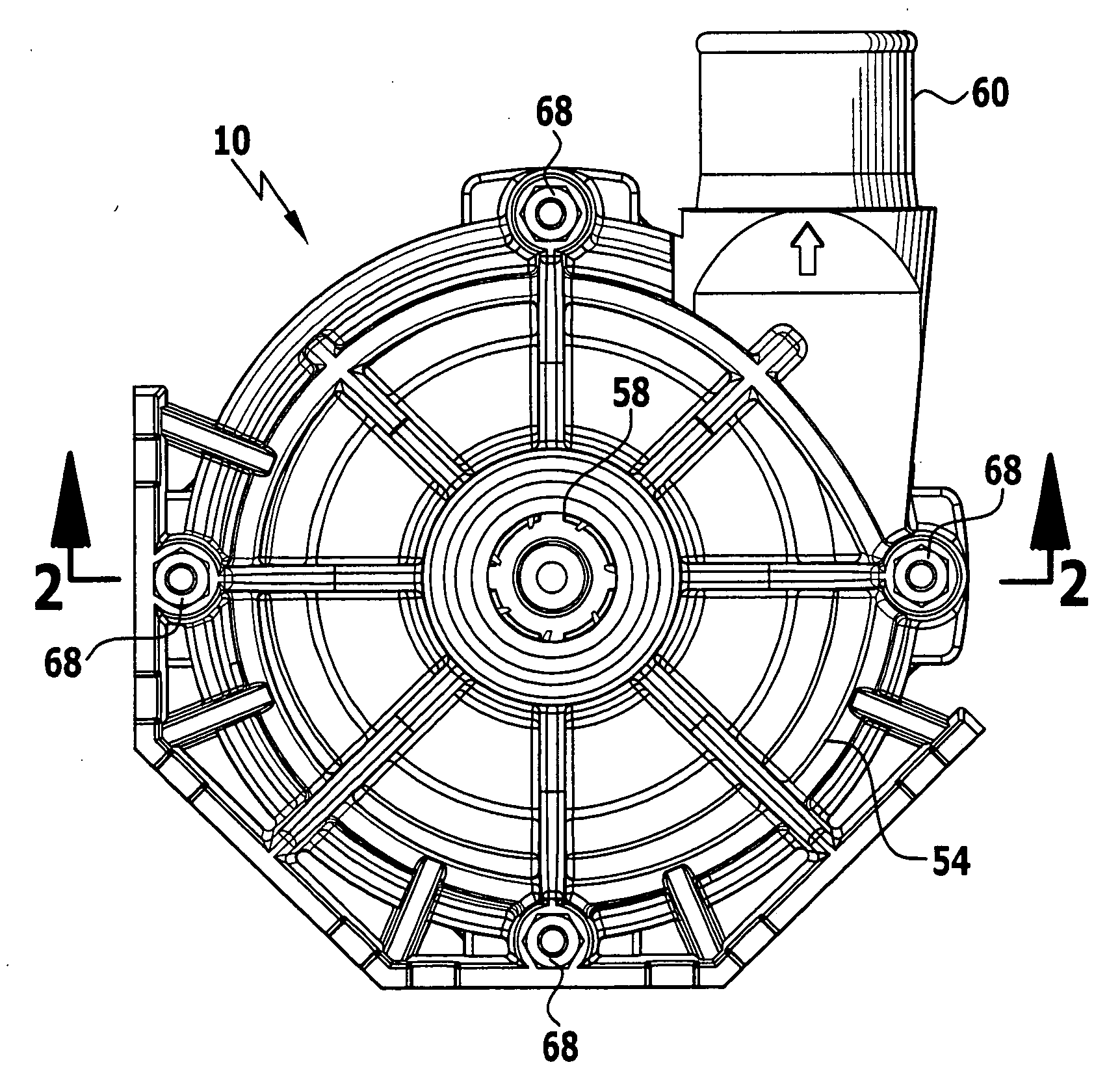
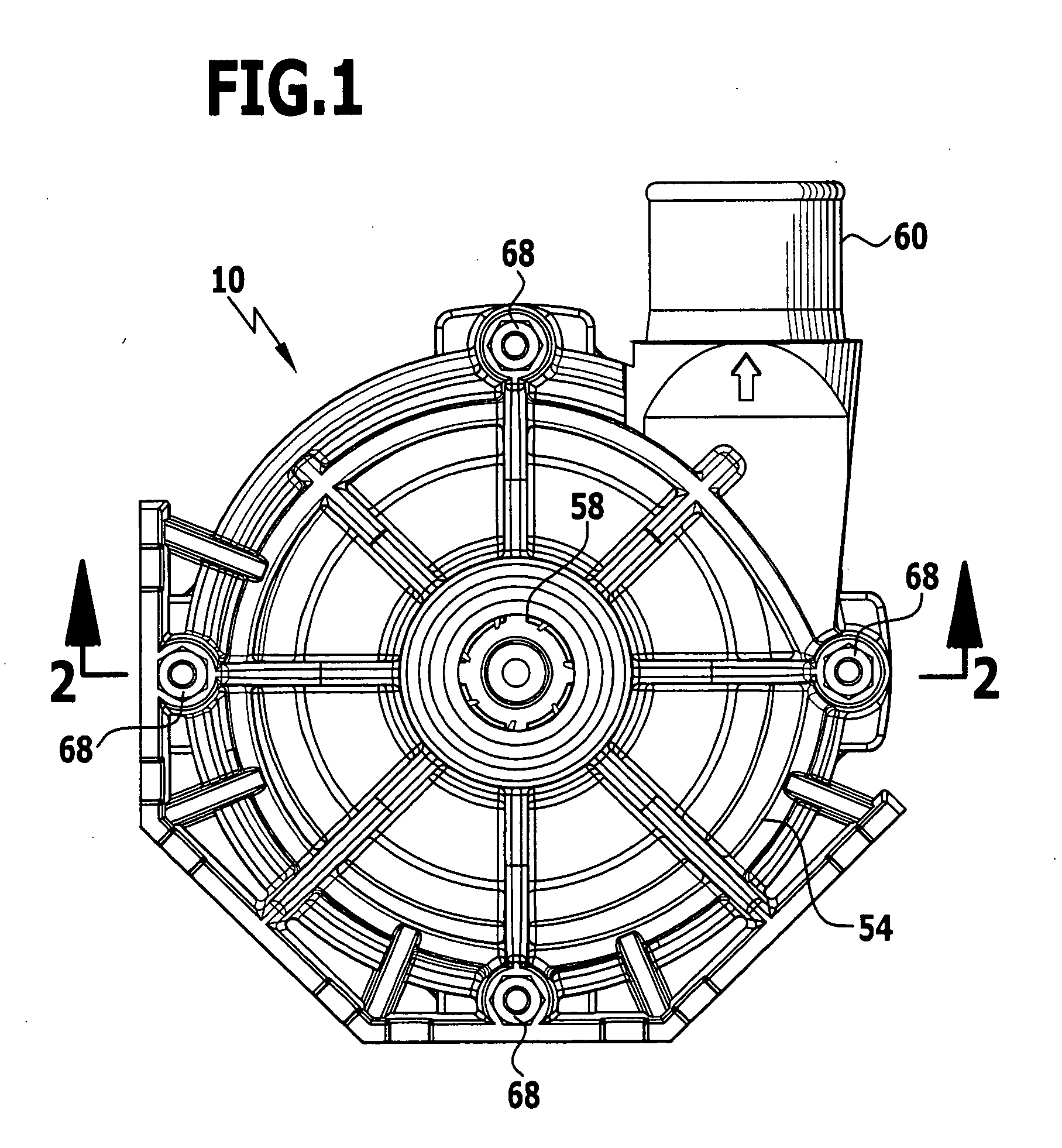
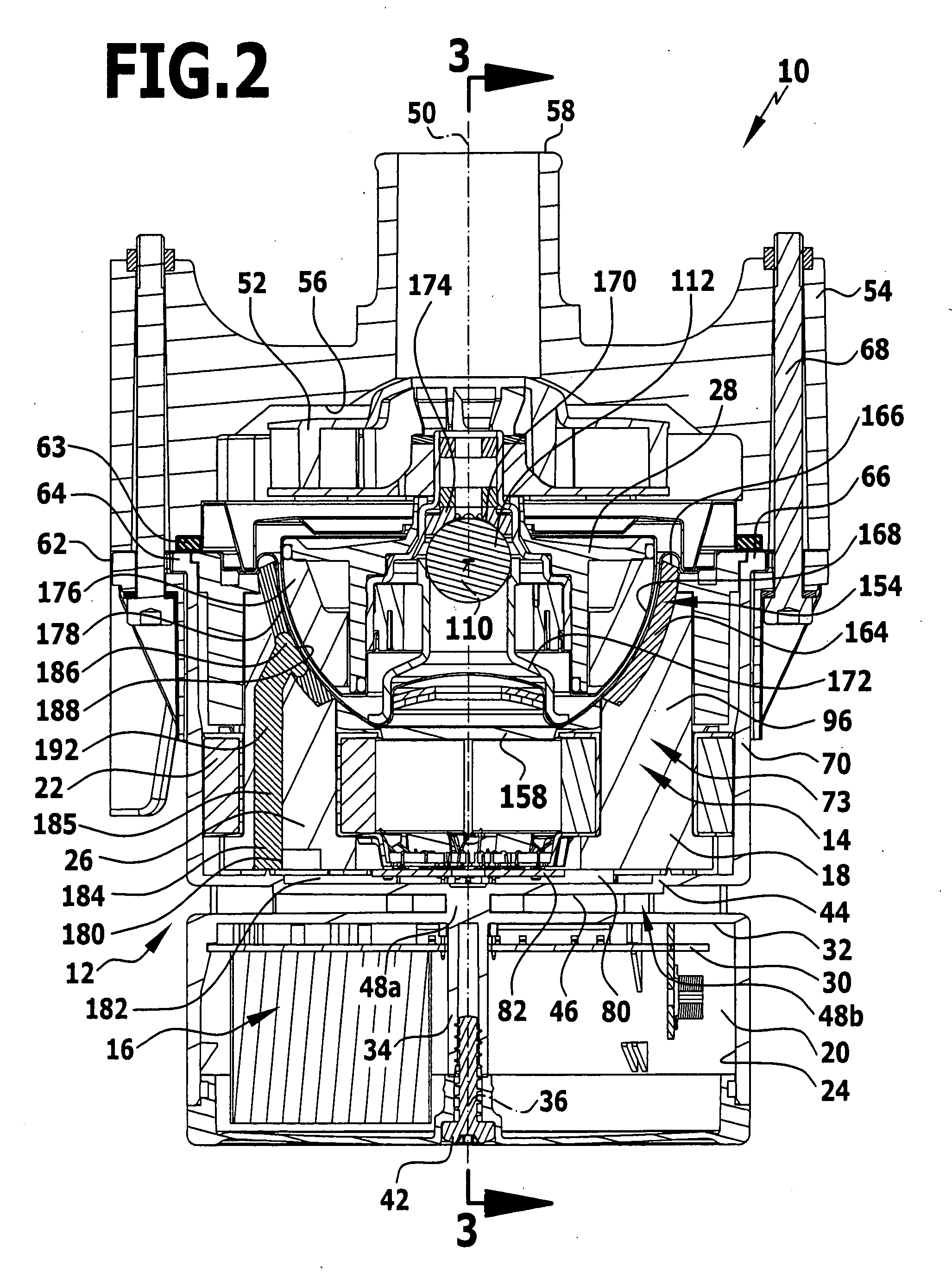
[0059]An embodiment of a circulation pump in accordance with the invention, which is shown in FIGS. 1 to 3 and denoted there by 10, comprises a housing 12. Disposed in the housing 12 is an electric motor 14 with an electric motor circuit 16.

[0060]The housing 12 has a first chamber 18 and a second chamber 20 separate from the first chamber 18. The first chamber 18 has a substantially cylindrical interior 22. The second chamber 20 likewise has a substantially cylindrical interior 24.

[0061]In the first chamber 18 a stator 26 and a rotor 28 of the electric motor 14 are disposed. The first chamber 18 in this case has a first sub-chamber that is exposed to the conveyed liquid. In a second sub-chamber of the first chamber 18 the stator is seated, wherein the second sub-chamber is separated in a liquid-proof manner from the first sub-chamber. The rotor 28 is seated in the first sub-chamber.

[0062]Disposed in the second chamber 20 is a carrier 30, which in particular is a carrier printed circ...


PUM


Abstract

In order to provide a circulation pump for a conveyed liquid, comprising an electric motor, which is electronically commutated and has a rotor, a stator and a motor circuit, and an impeller that is connected in a rotationally fixed manner to the rotor, with advantageous properties, it is provided that the electric motor has an evaluation device, by means of which a flow rate of conveyed liquid through the circulation pump can be determined from a rotational speed of the rotor and/or a power consumption of the electric motor, and at least one signal output is provided, at which a flow rate signal and/or flow rate-dependent switching signal can be supplied by the circulation pump.

Description

[0001]The present disclosure relates to the subject matter disclosed in German application number 10 2007 054 313.3 of Nov. 5, 2007, which is incorporated herein by reference in its entirety and for all purposes.BACKGROUND OF THE INVENTION[0002]The invention relates to a circulation pump for a conveyed liquid, comprising an electric motor, which is electronically commutated and has a rotor, a stator and a motor circuit, and an impeller that is connected in a rotationally fixed manner to the rotor.[0003]The invention further relates to a heating system for heating a liquid in a basin, comprising a flow-through region for liquid that is positioned outside a liquid-receiving space of the basin, a heater that is disposed at the flow-through region, a control device for the heater as well as a circulation pump.[0004]The invention further relates to a method of determining the flow rate of a liquid through a pipe.[0005]From DE 103 22 366 A1 a heating device for a liquid in a basin is know...

Claims


Application Information

Patent Timeline
Patent Type & Authority Applications(United States)
IPC IPC(8): F24D3/00F04B49/06G01F1/56
CPCF04D13/06F04D15/0088G01F25/0007G01F11/22G01F1/206F04D13/0633F04D29/0467G01F25/10
Inventor LAING, OLIVERLAING, KARSTEN
Owner ITT MFG ENTERPRISES LLC
Why Eureka
Try Eureka