Automatic optical fiber gyroscope winding machine and optical fiber winding method

A fiber optic gyroscope and winding machine technology, applied in the direction of measuring devices, instruments, etc., can solve the problems of uneven wiring and gaps, and achieve the effect of uniform wiring and improving work efficiency.

Active Publication Date: 2015-07-22
合肥正阳光电科技有限责任公司
View PDF6 Cites 15 Cited by
  • Summary
  • Abstract
  • Description
  • Claims
  • Application Information

AI Technical Summary

Problems solved by technology

[0003] The existing fiber optic gyroscope winding device can only perform semi-automatic manual winding, and because there is no assistance f

Method used


Image

  • Automatic optical fiber gyroscope winding machine and optical fiber winding method
  • Automatic optical fiber gyroscope winding machine and optical fiber winding method
  • Automatic optical fiber gyroscope winding machine and optical fiber winding method

Examples


Example Embodiment

[0034] The present invention will be further described below in conjunction with the accompanying drawings:

[0035] First make all servo motors find their origin. Determine the position of 0mm on the respective rails.
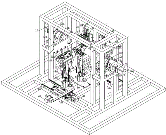
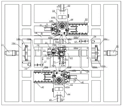
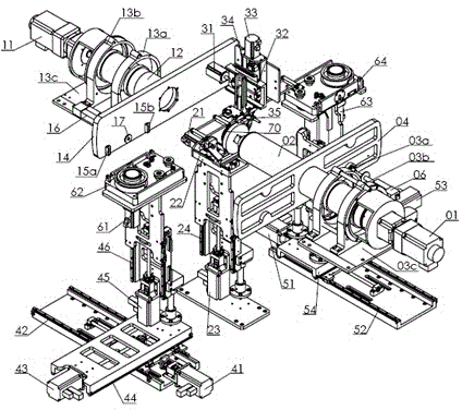
[0036] The optical fibers are then placed through the front pay-off reels 62a, 62b, 62c, 62d, 62e, the front guide wheel 25a, the take-up reel frame 70a, the rear guide wheel 25b, and the rear pay-off reels 65e, 65d, 65c, 65b, 65a. At this time the status is as image 3 , 4 shown.

[0037] Control the action of the rear electric push rod 06, loosen the main shaft circlip 07, so that the rear moving base 50 moves behind the base x-axis guide rail 52 to 56mm, and the base y-axis guide rail 54 moves to -51.6mm. The z-axis guide 56 of the rear base moves to 24mm, the x-axis guide 52 of the back base moves to 74.3mm, the z-axis guide 56 of the back base moves to 0mm, and the back electric push rod 06 moves to tighten the spindle clamp. At this time, the base 6...


PUM


Abstract

The invention relates to an automatic optical fiber gyroscope winding machine and an optical fiber winding method. The optical fiber gyroscope winding machine comprises a rack, a take-up tray, a spindle system, a sub-spindle system, a foot pressing system, a guiding system, a forward moving base, a backward moving base, a front pay-off tray base and a rear pay-off tray base. The optical fiber winding method comprises the processes of preparing, hanging a rear pay-off tray, removing the rear pay-off tray, hanging a front pay-off tray, removing the front pay-off tray, winding and arranging optical fibers. According to the technical scheme, the winding machine and the winding method can eliminate the drawbacks in the prior art, achieves automatic optical fiber winding, has the characteristics of uniform winding arrangement, no gap and the like, and can greatly improve the operation efficiency.

Description

technical field [0001] The invention relates to the technical field of optical fiber winding machines, in particular to an automatic optical fiber gyro winding machine and an optical fiber winding method. Background technique [0002] The fiber optic gyroscope winding machine is a kind of equipment used for the production of fiber optic rings for fiber optic gyroscopes and for completing the fiber optic winding process. In the process of winding the fiber optic ring by the machine, the relevant program of the equipment itself completes the winding process of the fiber optic ring, reducing the influence of human factors in the process of winding the fiber optic ring. The quality of the fiber ring is mainly guaranteed by the control accuracy of the machine itself. This can improve the consistency of product quality and provide equipment guarantee for mass production of optical fiber rings. The most critical technology of the fiber optic gyroscope is the winding of the fiber...

Claims


Application Information

Patent Timeline
IPC IPC(8): G01C25/00
CPCG01C25/00
Inventor 汪畅马文涛杨振罗家童刘斌
Owner 合肥正阳光电科技有限责任公司
Why Eureka
Try Eureka