Winding method for integrated magnetic component winding

A winding method and technology of components, applied in electrical components, transformer/inductor coil/winding/connection, transformer/inductor components, etc., can solve the problem of poor electrical performance and consistency of products, inability to control tension, Problems such as uneven wiring, to achieve the effect of improving consistency and stability, stable internal structure of the coil, and uniform wiring

Active Publication Date: 2019-11-12
SHENZHEN CLICK TECH +4
View PDF5 Cites 6 Cited by
  • Summary
  • Abstract
  • Description
  • Claims
  • Application Information

AI Technical Summary

Problems solved by technology

[0004] The main purpose of the present invention is to propose a winding method for integrated magnetic component windings, which uses a machine to complete the winding, and controls the transformer bobbin and the inductor bobbin to rotate separately and / or simultaneously when winding each winding coil through a fixed fixture. Complete the winding of transformer windings and inductance windings to overcome the problems of poor electrical performance and consistency of products caused by the current manual winding methods, which are inefficient, unable to control tension, and uneven wiring

Method used


Image

  • Winding method for integrated magnetic component winding
  • Winding method for integrated magnetic component winding
  • Winding method for integrated magnetic component winding

Examples


Embodiment Construction

[0017] The present invention will be further described below in conjunction with the accompanying drawings and specific embodiments.

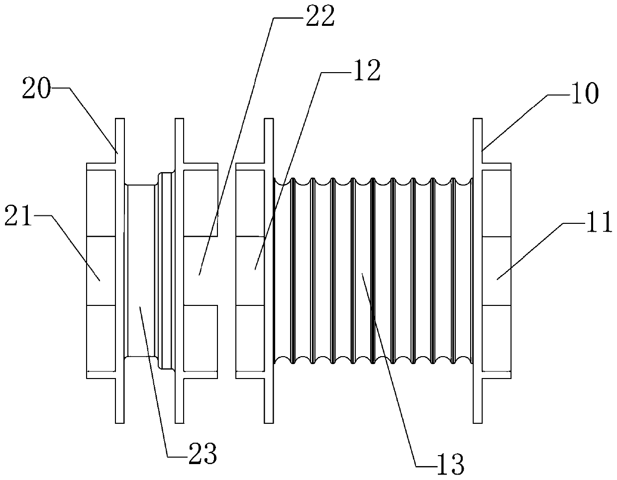
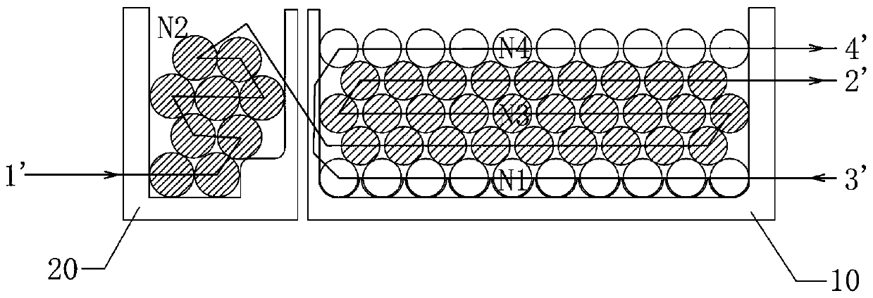
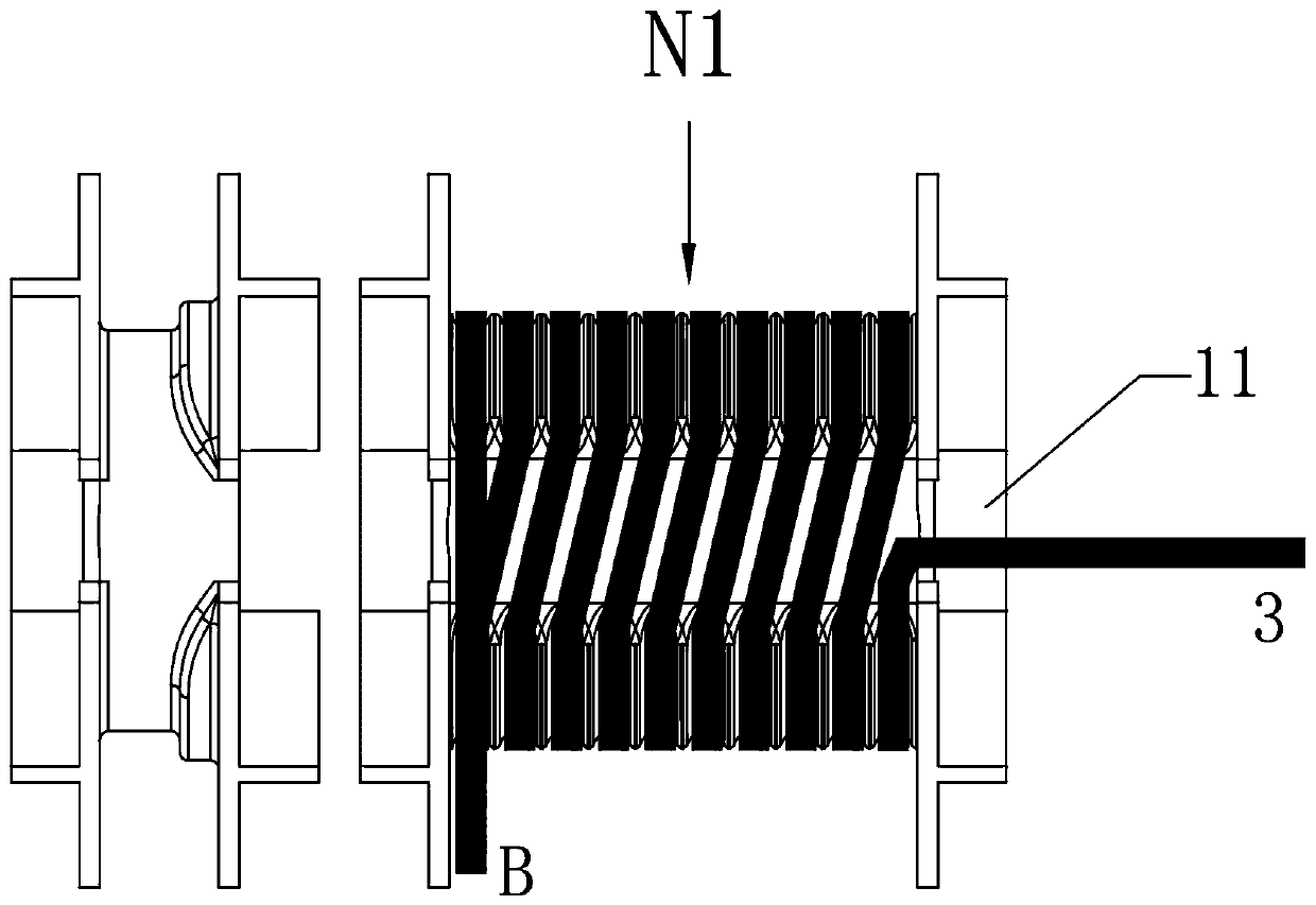
[0018] Current magnetic components require not only small size and high integration, but also higher power density and more stable electrical performance. For the integrated magnetic components that share the magnetic core of the transformer and the inductor, the winding requirements are relatively high when making the winding. The winding method needs to increase the power density as much as possible, and at the same time ensure the stability of the electrical performance and the consistency of the product. Good sex. In view of this, the present invention proposes a winding method for windings of transformers and inductance integrated magnetic components, by controlling the transformer bobbins and inductance bobbins to rotate separately / simultaneously on the automatic winding machine to complete the automatic winding of multi-layer coils with ...


PUM


Abstract

The invention discloses a winding method for an integrated magnetic component winding, comprising placing a transformer skeleton, an inductor skeleton and wires at corresponding positions of an automatic winding machine; rotating the transformer skeleton to wind a first group of wires around the transformer skeleton to form a part of a secondary coil, and not cutting off a lead-out end; rotating the inductor skeleton to wind a second group of wires around the inductor skeleton to form an inductor winding, and not cutting off a lead-out end; successively engaging the wire at the lead-out end ofthe inductor winding with a wire duct at the other end of the inductor skeleton and a wire duct at the other end of the transformer skeleton, simultaneously rotating the transformer skeleton and theinductor skeleton in the same direction in order to wind the second group of wires around a part of the secondary coil to form a primary coil, introducing the lead-out end into the wire duct and thencutting off the lead-out end; using the lead-out end of a part of the secondary coil as the starting end of the other part of the secondary coil, and simultaneously rotating the transformer bobbin andthe inductor bobbin in the same direction in order to winding the first group of wires around the primary coil to form the other part of the secondary coil, introducing the lead-out end into the wireduct and then cutting off the lead-out end.

Description

technical field [0001] The invention relates to magnetic components, in particular to a winding method for integrated magnetic components. Background technique [0002] Magnetic components are widely used in new energy vehicles, photovoltaic / wind power generation, power harmonic control, inverters, electronic information, UPS, PC and other fields. As one of the core devices, the magnetic component has parameters such as its size that directly affect the product quality. With the change of the use environment and different application fields, the performance of the components will also vary greatly. Especially in the field of new energy vehicles, the requirements for component volume, weight and application environment are extremely high. Therefore, it is imperative to develop a high-power-density, highly-integrated vehicle-mounted magnetic component. At present, when making magnetic components integrated with transformers and inductors, the traditional winding method is m...

Claims


Application Information

Patent Timeline
IPC IPC(8): H01F41/064H01F41/094H01F41/096H01F27/30H01F27/28H01F27/29
CPCH01F27/2823H01F27/29H01F27/306H01F41/064H01F41/094H01F41/096
Inventor 周正国曾海峰肖铿
Owner SHENZHEN CLICK TECH
Why Eureka
Try Eureka