
A high-power crimping type igbt package module fixture

A packaging module, crimping technology, applied in the direction of electrical components, semiconductor/solid-state device manufacturing, circuits, etc., can solve the limited tensile force of ordinary metal insulating rods, the unsatisfactory heat dissipation effect of ordinary radiators, and the difficulty of applying force to the overall fixture and other problems, to achieve the best anti-oxidation and anti-corrosion performance, easy production and assembly, disassembly and maintenance, and low thermal expansion rate

Active Publication Date: 2018-01-19
GLOBAL ENERGY INTERCONNECTION RES INST CO LTD +1
View PDF3 Cites 0 Cited by
  • Summary
  • Abstract
  • Description
  • Claims
  • Application Information

AI Technical Summary

Problems solved by technology

[0003] Nowadays, IGBT, as a mainstream device in the world, has developed to the fifth generation of commercialization, and the packaging methods of IGBT have also been diversified. In view of the diversification of packaging methods, the clamping methods of crimping IGBT packaging module fixtures are also various. The relatively mature crimping type IGBT package module fixture currently has natural cooling vertical type and natural cooling horizontal type, the clamping force is 10KN, and a single insulating rod is pressed against the top. The existing problem is the working condition of the crimping type IGBT package module. Uneven lower force, limited tensile force of ordinary metal insulating rods, difficulty in applying force to the overall fixture, low assembly accuracy, unsatisfactory heat dissipation effect of ordinary radiators, small operating current, small capacity, and low reliability, etc.

Method used


Image

  • A high-power crimping type igbt package module fixture
  • A high-power crimping type igbt package module fixture
  • A high-power crimping type igbt package module fixture

Examples


Embodiment Construction

[0046] In order to better understand the present invention, the content of the present invention will be further described below in conjunction with the accompanying drawings and examples.

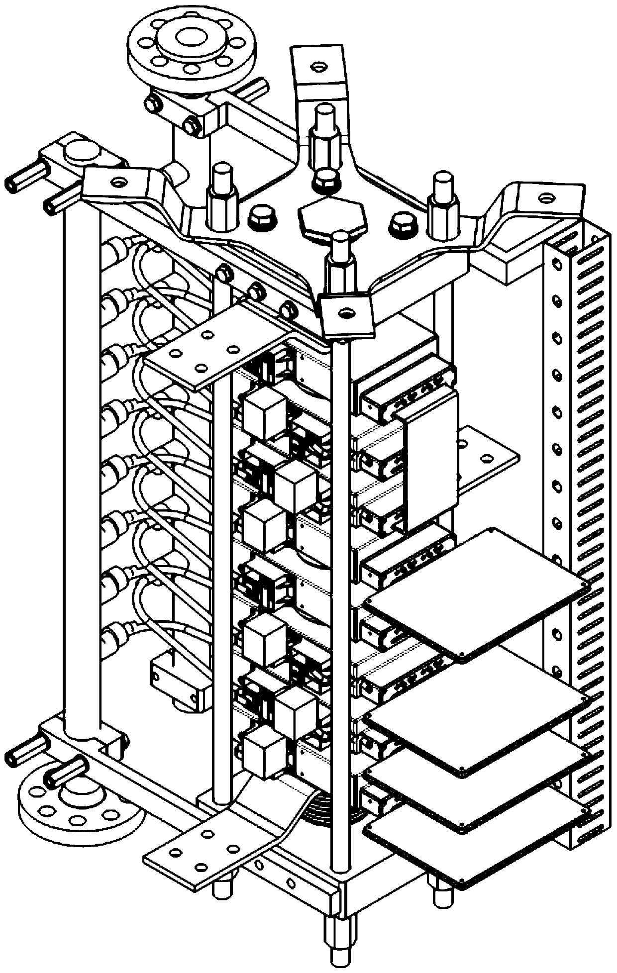
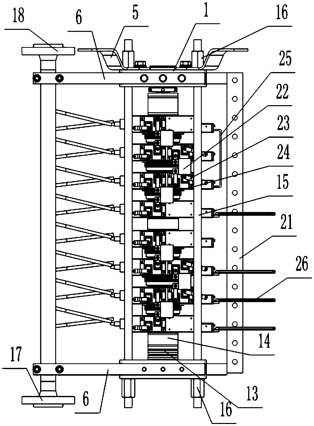
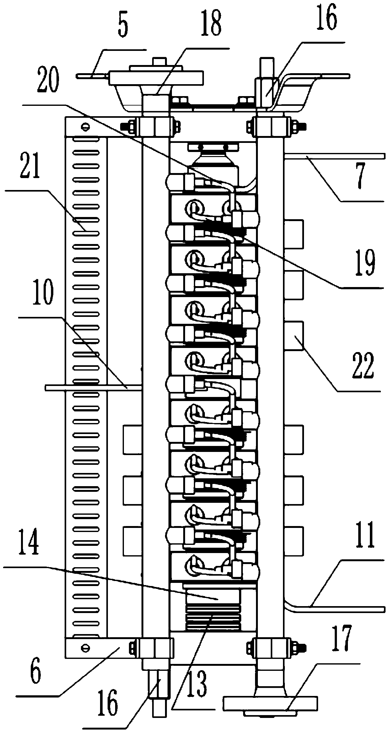
[0047] The present invention provides a high-power crimping type IGBT packaging module fixture, its three-dimensional structure diagram is as follows figure 1 As shown, it includes: upper fixture flange set, upper lead-out row 7, upper water-cooling heat dissipation set, middle lead-out row fixing block, lower water-cooling heat dissipation set, lower end lead-out row 11, lower load-bearing flange set, high-performance vertical Straight insulating support rod, radiator waterway assembly, wire channel assembly, capacitor assembly, damping resistance assembly, short circuit board 25, drive board 26;

[0048] The upper clamp set is longitudinally arranged on the upper surface of the upper lead-out row 7; the lower surface of the upper lead-out row 7 is longitudinally connected to the upper wa...


PUM


Abstract

The invention provides a high-power crimping type IGBT encapsulation module fixture comprising an insulation supporting rod arranged vertically, and a lower end bearing flange component set, a lower end drainage bar, a lower water cooling component set, a middle drainage bar, an upper water cooling component set, an upper end drainage bar and an upper end fixture flange component set which are arranged from bottom to top sequentially and horizontally. Two sides of the upper and lower water cooling component sets are provided with capacitor components and damping resistor components, and the other two sides are provided with radiator waterway components, short circuit plates, drive plates and guide wire groove components; the upper and lower water cooling component sets comprise water cooling radiators which are parallel to each other vertically and which clamp a crimping type IGBT encapsulation module, and nickel is planted on the surfaces of the water cooling radiators. The fixture is simpler and more compacted in whole structure, more convenient to manufacture and assemble and more reasonable in layout and has higher reliability and better heat radiating performance.

Description

technical field [0001] The invention relates to a microelectronic package fixture, in particular to a high-power crimping type IGBT package module fixture. Background technique [0002] Insulated gate bipolar transistor (IGBT) combines the gate voltage control characteristics of MOSFET and the low on-resistance characteristics of BJT, and has the characteristics of large input impedance, low driving power, low switching loss, operating frequency, high voltage, and high current. , is an almost ideal semiconductor high-power switching device with broad development and application prospects. , rail transit, aviation, ships, marine engineering and other fields. [0003] Nowadays, IGBT, as a mainstream device in the world, has developed to the fifth generation of commercialization, and the packaging methods of IGBT have also been diversified. In view of the diversification of packaging methods, the clamping methods of crimping IGBT packaging module fixtures are also various. Th...

Claims


Application Information

Patent Timeline
Patent Type & Authority Patents(China)
IPC IPC(8): H01L21/687
CPCH01L21/68707
Inventor 苏莹莹陈中圆温家良王志霞
Owner GLOBAL ENERGY INTERCONNECTION RES INST CO LTD
Learn More