Heating cooker
A cooker and container technology, applied in the field of heating cookers, can solve the problems of hot air ejection, shape deformation of heated objects, and difficulty in uniform heating, etc., to achieve uniform heating effect
- Summary
- Abstract
- Description
- Claims
- Application Information
AI Technical Summary
Problems solved by technology
Method used
Image
Examples
Embodiment approach 1
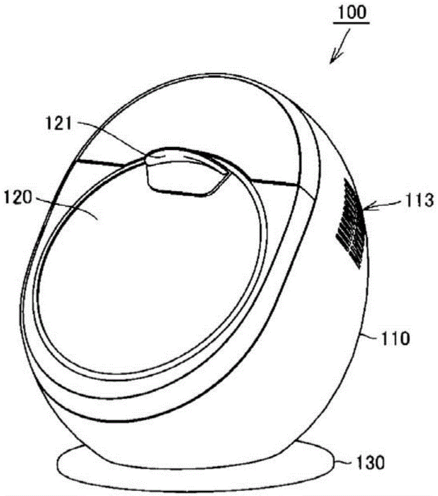
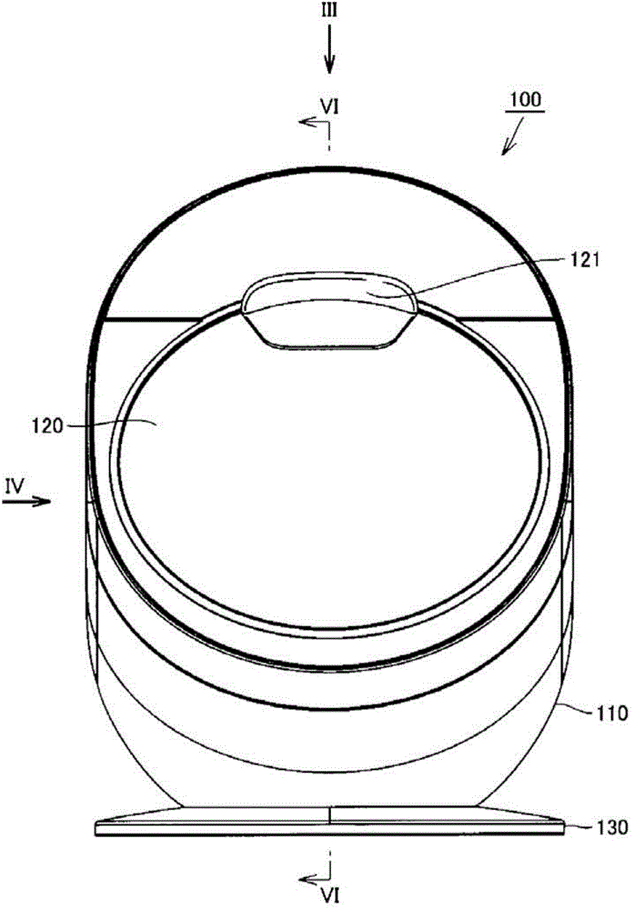
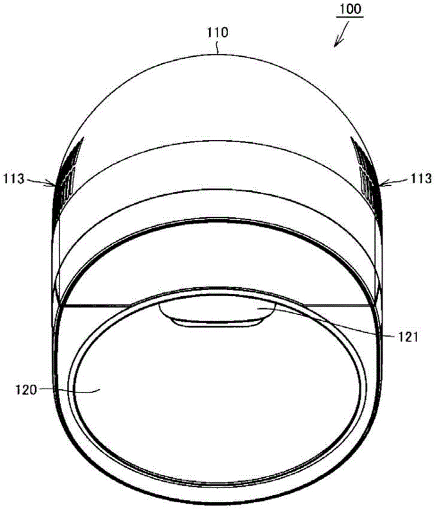
[0050] figure 1 It is a perspective view which shows the appearance of the heating cooker which concerns on Embodiment 1 of this invention. figure 2 It is a front view which shows the appearance of the heating cooker which concerns on this embodiment. image 3 From figure 2 The top view of the heating cooker is observed from the direction shown by the arrow III. Figure 4 From figure 2 The side view of the heating cooker observed from the direction indicated by the arrow IV. Figure 5 It is a perspective view which shows the state which opened the door of the heating cooker which concerns on this embodiment. Image 6 From figure 2 The sectional view of the heating cooker observed in the direction of the arrow of line VI-VI.
[0051] Figure 7 It is a sectional view schematically showing the structure of the heating cooker of the same embodiment. Figure 8 It is a front view which schematically shows the structure of the heating cooker which concerns on this Embodim...
Embodiment approach 2
[0131] Figure 19 It is a vertical cross-sectional view showing the structure of the heating cooker according to Embodiment 2 of the present invention. Figure 20 It is a cross-sectional view showing the structure of the heating cooker of this embodiment. Figure 21 It is a cross-sectional view showing the state in which the opening and closing door is opened and the container is taken out in the heating cooker of this embodiment. Figure 22 It is a longitudinal sectional view which shows the main-body part of a housing in the heating cooker of this embodiment. Figure 23 It is a longitudinal sectional view of the opening and closing door in the heating cooker of this embodiment.
[0132] Such as Figures 19-21 As shown, the heating cooker 200 according to Embodiment 2 of the present invention includes: a box body; a container 250, which is stored in the box body with the central axis inclined at a predetermined angle relative to the vertical direction, and accommodates an ...
Embodiment approach 3
[0171] Figure 24 It is a perspective view which shows the appearance of the heating cooker which concerns on Embodiment 3 of this invention. Figure 25 It is a perspective view which shows the structure of the angle adjustment mechanism of the heating cooker of this embodiment. Figure 25 Only the base 330 is shown in perspective.
[0172] The heating cooker 300 according to Embodiment 3 of the present invention includes: a box body; a container, which is accommodated in the box in a state in which the central axis is inclined at a predetermined angle with respect to the vertical direction, and accommodates an object to be heated; hot air; and a drive mechanism to make the container rotate around the central axis.
[0173] Such as Figure 24 , Figure 25 As shown, the box includes a substantially hemispherical main body 310 and a switch door 320 connected to the main body 310 . The box is supported to have a variable inclination angle with respect to the base 330 .
[0...
PUM
 Abstract
Description
Claims
Application Information
 - R&D
- Intellectual Property
- Life Sciences
- Materials
- Tech Scout
- Unparalleled Data Quality
- Higher Quality Content
- 60% Fewer Hallucinations
Browse by: Latest US Patents, China's latest patents, Technical Efficacy Thesaurus, Application Domain, Technology Topic, Popular Technical Reports.
© 2025 PatSnap. All rights reserved.Legal|Privacy policy|Modern Slavery Act Transparency Statement|Sitemap|About US| Contact US: help@patsnap.com


