Method for producing a valve device and corresponding valve device

A valve device and valve block technology, which is applied in the field of valve device manufacturing, can solve problems such as large material consumption, and achieve the effects of high surface quality and material saving

Inactive Publication Date: 2015-07-22
ROBERT BOSCH GMBH
View PDF6 Cites 2 Cited by
  • Summary
  • Abstract
  • Description
  • Claims
  • Application Information

AI Technical Summary

Problems solved by technology

Correspondingly, not the entire extension of the valve block is used for the abutment...

Method used


Image

  • Method for producing a valve device and corresponding valve device
  • Method for producing a valve device and corresponding valve device
  • Method for producing a valve device and corresponding valve device

Examples


Embodiment Construction

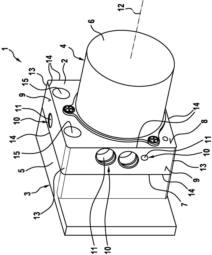
[0026] figure 1 A valve arrangement 1 is shown with a valve block 2 , which can also be referred to as a hydraulic assembly. Furthermore, valve device 1 has a plurality of accessories 3 and 4 , of which, for example, accessory 3 is present as a controller and accessory 4 is present as a pump motor, from which housing 5 or 6 respectively can be seen. The accessories 3 and 4 are fastened directly or indirectly to the valve block 2 , wherein they are respectively fastened against the contact surface 7 or 8 . Apart from the contact surfaces 7 or 8 present in the form of the end faces of the valve block 2 , the valve block has four sides 9 , only two of which are visible here. A number of fluid lines 10 are provided in the valve block 2 , only some of which are marked here as examples. For example, the fluid line 10 passes through at least one of the contact surfaces 7 and 8 or at least one of the side surfaces 9 or any desired combination of these surfaces when the opening 11 is...


PUM


Abstract

The invention relates to a method for producing a valve device (1) having a valve block (2) and at least one attachment part (3, 4) contacting a contact surface (7, 8) of the valve block (2), wherein the valve block (2) is produced by means of extrusion molding in an extrusion direction (12) and subsequent separation perpendicular to the extrusion device (12). According to the invention, the contact surface (7, 8) is formed for the attachment part (3, 4) by the separation. The invention further relates to a valve device (1).

Description

technical field [0001] The invention relates to a method for producing a valve device with a valve block and at least one attachment which bears against an abutment surface of the valve block, wherein by pressing in the extrusion direction and then perpendicular to the extrusion The separation of the directions makes the valve block. Furthermore, the invention relates to a valve arrangement. Background technique [0002] The valve device is, for example, a component of a driver assistance system of a motor vehicle, in particular an ABS driver assistance system and / or an ESP driver assistance system. The valve arrangement has at least one valve block, which can also be referred to as a hydraulic unit. In addition, accessories are provided, which can be present, for example, in the form of a controller or a pump or a pump motor. In this regard the accessory is preferably a motorized accessory or an electronic accessory. Of course, however, other accessories, in particular ...

Claims


Application Information

Patent Timeline
IPC IPC(8): B23P13/04B23P15/00B60T8/36B60T13/66F15B13/08H05K5/00
CPCB23P15/001B23P13/04B60T8/368F16K27/003
Inventor M·迈尔A·巴雷斯A·韦
Owner ROBERT BOSCH GMBH
Why Eureka
Try Eureka