Special clamp for realizing multi-point clamping

A special fixture and multi-point technology, applied in the field of workpiece clamping, can solve the problems of easy loosening of the workpiece, easy to scratch the surface, and reduce the stability and reliability of the clamping, so as to improve the stability and reliability and improve the clamping The effect of stiffness

Inactive Publication Date: 2015-07-29
SUZHOU VOCATIONAL UNIV
View PDF6 Cites 2 Cited by
  • Summary
  • Abstract
  • Description
  • Claims
  • Application Information

AI Technical Summary

Problems solved by technology

[0002] A cam multi-point clamping device is disclosed in the prior art 201320786050.8, which includes a base and a cam disc, wherein a rotating shaft, a rotating handle and a clamping arm with a clamping head at one end are also provided, and the rotating shaft and the cam The center of the bottom of the disc is fixedly connected, the rotating handle is perpendicular to the rotating shaft and is fixedly connected with it, and there are multiple sets of clamping arms whose middle parts are hinged on the base. section; when working, the end of the clamping arm is pushed outward through the upper radius of the cam disc from small to large, and since the middle part of the clamping arm is hinged on the base, the head of the clamping arm swings downward, thus through friction The workpiece is clamped by force; when the existing clamping is performed, the head of the clamping arm clamp swings downward to clamp the workpiece, which is easy to scratch the processed surface, and the workpiece is clamped by friction force, so that the workpiece can be easily processed in the subsequent processing. Looseness reduces the stability and reliability of clamping. For this reason, we have developed a special fixture for multi-point clamping, which can improve the clamping stiffness of the workpiece and improve the stability and reliability of clamping.

Method used


Image

  • Special clamp for realizing multi-point clamping
  • Special clamp for realizing multi-point clamping

Examples


Embodiment Construction

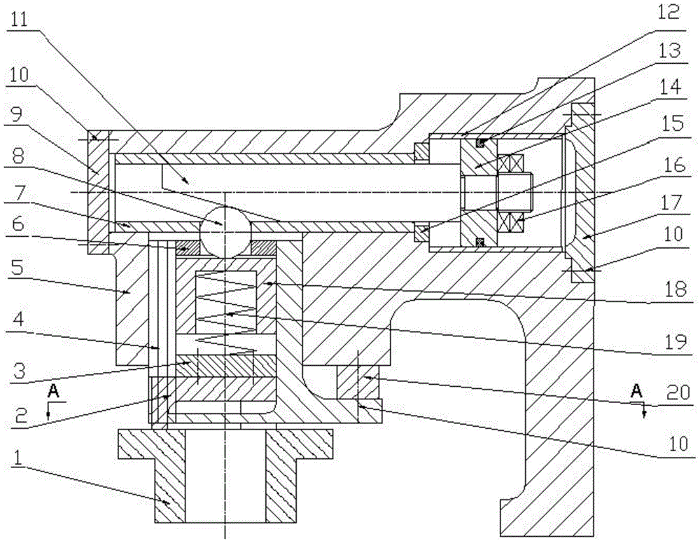
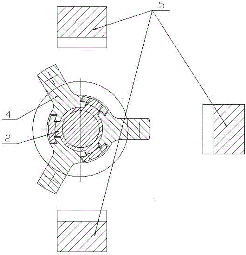
[0016] The present invention will be further described in detail below in conjunction with the accompanying drawings and specific embodiments.

[0017] attached Figure 1-2 It is a special fixture for realizing multi-point clamping according to the present invention, which includes a clamp body 5; a piston rod 11 arranged horizontally and capable of moving left and right is arranged in the clamp body 5; the two ends of the piston rod 11 are correspondingly provided with The left end cover 9 and the right end cover 17; the left end cover 9 and the right end cover 17 are respectively fixed on the clamp body 5 by screws 10 to play a sealing role; the lower side of the left end of the piston rod 11 is provided with a slope, and the right end is provided with a piston 14 and nut 16; the piston 14 is fixed on the piston rod 11 by the nut 16; a bushing 7 is arranged between the piston rod 11 and the clamp body 5; a piston bushing is arranged between the piston 14 and the clamp body 5...


PUM


Abstract

The invention relates to a special clamp for realizing multi-point clamping. The special clamp comprises a clamp body, wherein a piston rod which is in horizontal arrangement and can move is arranged in the clamp body, the lower side of one end of the piston rod is provided with an inclined surface, the other end of the piston rod is provided with a piston, a guide sleeve with the Y-shaped cross section is arranged in the clamp body and under a position, provided with an inclined surface, of the piston, a spring sleeve, a spring and a press block which can vertically move are sequentially arranged in the guide sleeve from top to bottom, a rolling post is arranged between the spring sleeve and the inclined surface, the two sides of the rolling post are provided with position limiting rings, the lower end of the press block is provided with three press claws in circumferential distribution, and the three press claws can extend out of the guide sleeve for tightly pressing a workpiece. The special clamp has the advantages that through hydraulic driving, three press claws arranged on the press block are simultaneously in contact with the workpiece, the installing and clamping rigidity of the workpiece are improved, and the stability and the reliability of the installation and clamping are improved.

Description

technical field [0001] The invention relates to the field of workpiece clamping, in particular to a special clamp for realizing multi-point clamping. Background technique [0002] A cam multi-point clamping device is disclosed in the prior art 201320786050.8, which includes a base and a cam disc, wherein a rotating shaft, a rotating handle and a clamping arm with a clamping head at one end are also provided, and the rotating shaft and the cam The center of the bottom of the disc is fixedly connected, the rotating handle is perpendicular to the rotating shaft and is fixedly connected with it, and there are multiple sets of clamping arms whose middle parts are hinged on the base. section; when working, the end of the clamping arm is pushed outward through the upper radius of the cam disc from small to large, and since the middle part of the clamping arm is hinged on the base, the head of the clamping arm swings downward, thus through friction The workpiece is clamped by force...

Claims


Application Information

Patent Timeline
Patent Type & Authority Applications(China)
IPC IPC(8): B25B11/00
CPCB25B11/00B23Q3/00
Inventor 刘丹刘悦洋
Owner SUZHOU VOCATIONAL UNIV
Why Eureka
Try Eureka