
Variable diameter dies on pipe production line

A production line and pipe technology, applied in the field of variable-diameter molds, can solve the problems of inconvenient replacement operation, large die volume, and long replacement time, and achieve the effects of improving production operation efficiency, saving operation time, and convenient replacement.

Active Publication Date: 2017-04-12
CHONGQING WEIXING NEW BUILDING MATERIALS
View PDF4 Cites 0 Cited by
  • Summary
  • Abstract
  • Description
  • Claims
  • Application Information

AI Technical Summary

Problems solved by technology

[0004] 1. Because the die and mandrel of the existing extrusion die are fixed-caliber dies, when producing pipes with different diameters, the extrusion die needs to be replaced. Each die change is not only time-consuming, but also requires more energy It is used to adjust the gap between the die and the mandrel (the gap is the thickness of the pipe), so it affects the production efficiency of the pipe
[0005] 2. The die in the existing extrusion die is large in size and heavy in weight (about 10kg). The replacement operation is not only inconvenient, but also has the potential safety hazard of falling and pinching the feet during the replacement process.
[0006] 3. Before each mold change, the heating ring wrapped on the outer surface of the die must be removed first, and then the mold can be changed; thus resulting in a long time for mold change (needs 10 to 15 minutes) and frequent disassembly and assembly make heating ring is easily damaged
[0008] In summary, the extruding die replacement process in the prior art will be cumbersome, seriously affecting the production efficiency of the pipe

Method used


Image

  • Variable diameter dies on pipe production line
  • Variable diameter dies on pipe production line
  • Variable diameter dies on pipe production line

Examples


Embodiment Construction

[0039] The present invention will be further described in detail below in conjunction with the accompanying drawings.

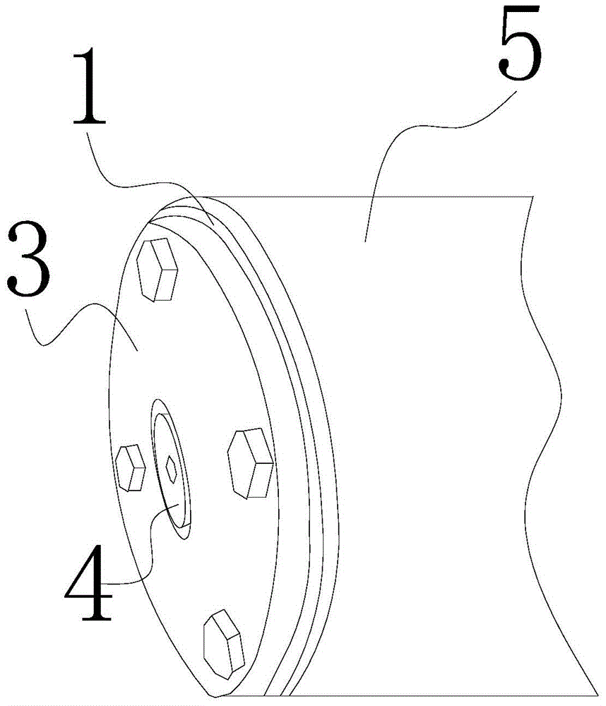
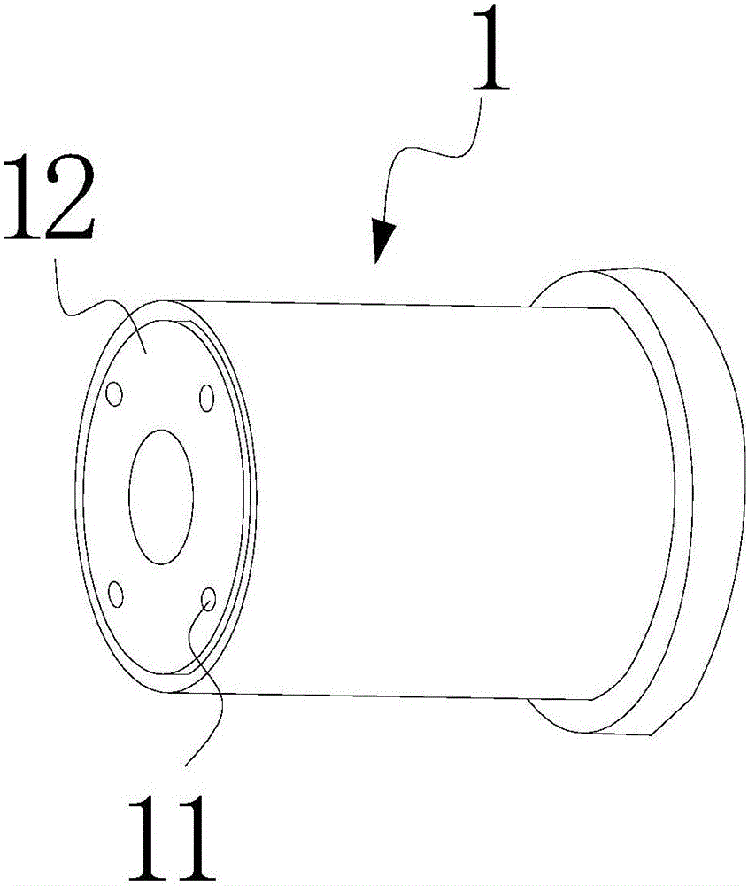
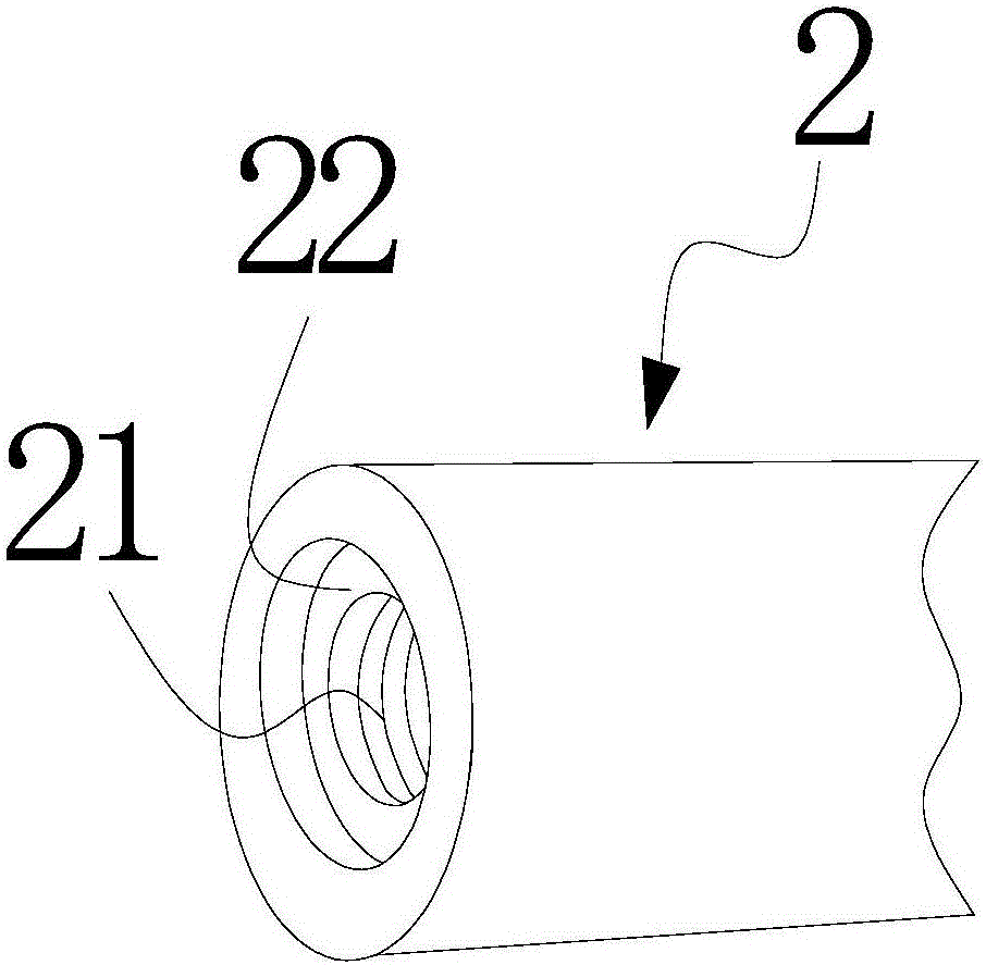
[0040] Such as Figure 1 to Figure 7 As shown, a variable diameter die on a pipe production line includes a die 1 and a core die 2 installed on the extruder body;

[0041] It also includes an end plate 3, the end plate 3 is detachably fixed on the extrusion end of the die 1, and the end plate 3 has a perforation 31 connected with the die 1;

[0042] It also includes a cylindrical core mold end 4 as a whole, one end of the core mold end 4 is fixed with a central boss 41, the central boss 41 has external threads, and the other end of the core mold end 4 has Tightening part for external thread tightening;

[0043] One end of the mandrel 2 adjacent to the die 1 has an internal thread 21 matching the external thread; the central post 41 of the mandrel end 4 passes through the perforation 31 and is connected with the mandrel 2 Threaded connection; the main part ...


PUM


Abstract

The invention belongs to the field of pipe production lines, in particular to a reducing mold on a pipe production line. The reducing mold on the pipe production line comprises a neck mold and a core mold that are mounted on an extruder body. The reducing mold is characterized by further comprising an end plate and an entirety columnar core mold end head, wherein the end plate is detachably fixed at an extrusion end of the neck mold; a penetrable hole communicated with the neck mold is formed in the end plate; a center convex column is fixedly arranged at one end of the core mold end head and provided with external threads; a tightening part to tightly screw the external threads is arranged at the other end of the core mold end head; internal threads matched with the external threads are formed at one end, close to the neck mold, of the core mold; the center convex column of the core mold end head penetrates through the penetrable hole and is in threaded connection with the core mold; a main body part of the core mold end head traverses into the penetrable hole; and a clearance for extruding a pipe is reserved between the main body part and an internal wall of the penetrable hole. The reducing mold on the pipe production line is more convenient and quicker to use and can improve production efficiency.

Description

technical field [0001] The invention belongs to the field of pipe production lines, and in particular relates to a variable-diameter mold on a pipe production line. Background technique [0002] The pipe production line is an assembly line for pipe production. The main configurations include: automatic feeding machine, extruder, extrusion die, vacuum sizing spray box, tractor, cutting machine, stacker, etc. The above-mentioned extrusion die is installed at the head of the extruder. During the production of pipes, the polyethylene, polypropylene or polyvinyl chloride that has been compacted, melted, mixed and homogenized in the extruder is pushed by the screw in the extruder. To the extrusion die and extrude the pipe, so the extrusion die is the key building part of the pipe forming. [0003] At present, the extrusion die in the prior art includes a die and a core die; wherein, the die is fixed on the body of the extruder, and the core die passes through the die and is fixe...

Claims


Application Information

Patent Timeline
Patent Type & Authority Patents(China)
IPC IPC(8): B29C47/22B29C48/325
CPCB29C48/30B29C48/325
Inventor 赵银周绍强
Owner CHONGQING WEIXING NEW BUILDING MATERIALS
Learn More