Valve-type anti-blocking printer nozzle component

A nozzle assembly and printer technology, applied in the field of 3D printing, can solve the problems of nozzle blockage and limited anti-slip effect of the material guide pipe, and achieve the effect of reasonable structure and good thermal conductivity.

Active Publication Date: 2015-07-29
NANNING LIHAN INSTR EQUIP CO LTD
View PDF4 Cites 1 Cited by
  • Summary
  • Abstract
  • Description
  • Claims
  • Application Information

AI Technical Summary

Problems solved by technology

[0007] The above-mentioned utility models have all adopted the same technical means, i.e. prevent nozzle clogging with a good lubricating guide tube; this technical means can indeed play a certain anti-clogging effect, but it is not a solution to the clogging problem in essence, and When the unmelted silk material and the molten silk material stick together at the outlet of the feed throat and cause congestion, the anti-slip effect of the guide tube becomes limited
[0008] The nozzle clogging problem often occurs after the shutdown, because the heater has stopped working after the shutdown, the temperature in the nozzle cavity drops rapidly, and there is still some silk in the feed throat (hereinafter referred to as the residual), this part of the silk is in the gravity Under the action, it still moves to the nozzle cavity. When the temperature of the nozzle is not enough to completely melt this part of the filament, the filament will return to solid state. The joint between the material throat and the nozzle will cause the nozzle to be blocked

Method used


Image

  • Valve-type anti-blocking printer nozzle component
  • Valve-type anti-blocking printer nozzle component

Examples


Embodiment Construction

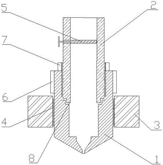
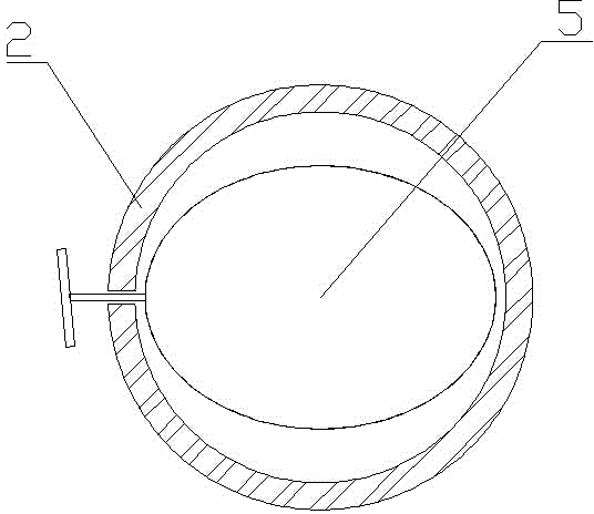
[0026] see figure 1 , the nozzle assembly of the valve-type anti-blocking printer of the present invention includes a nozzle 1, a feed throat 2, a heater 3, and a screw mechanism 4; the feed port of the nozzle 1 communicates with the discharge port of the feed throat 2 , the heater 3 is arranged on the outside of the nozzle and closely contacts the heated area of ​​the nozzle; the nozzle, the feed throat and the heater are all fixedly connected by a threaded mechanism 4; the transition between the nozzle and the feed throat is provided with a leak-proof Step 8, the screw mechanism fixedly connecting the nozzle 1 and the feed throat 2 is set on the inner wall of the upper cavity of the nozzle, and the outer wall of the feed throat is correspondingly provided with a reverse thread mechanism, and the thread of the screw mechanism extends beyond the feed inlet of the nozzle ; It also includes the silk material valve 5 arranged near the junction of the feeding throat and the nozzle...


PUM


Abstract

The invention discloses a valve-type anti-blocking printer nozzle component which comprises a nozzle, a feed throat pipe, a heater and a threaded mechanism, and further comprises a silk material valve, wherein the feed opening of the nozzle is communicated with the discharge opening of the feed throat pipe; the heater is arranged outside the nozzle, and is in tight contact with the heated area of the nozzle; the nozzle, the feed throat pipe and the heater are all fixedly connected with one another through the threaded mechanism; a leak-proof step is formed at the transitional part between the nozzle and the feed throat pipe; the threaded mechanism, through which the nozzle and the feed throat pipe are fixedly connected with each other, is arranged on the inner wall of the upper part cavity of the nozzle; a reversed threaded mechanism is correspondingly arranged on the outer wall of the feed throat pipe; the thread of the threaded mechanism extends out of the feed opening of the nozzle; the silk material valve is arranged near the joint of the feed throat pipe and the nozzle; when the heater stops heating, the feed throat pipe is closed by the silk material valve. The valve-type anti-blocking printer nozzle component is high in leak prevention and anti-blocking performance, sturdy and durable.

Description

technical field [0001] The invention relates to the technical field of 3D printing, in particular to an anti-leakage and anti-blocking nozzle assembly of a printer. Background technique [0002] At present, many 3D printers use "fusion deposition molding" technology. The so-called "fusion deposition molding" means that the whole process is to melt plastic in the nozzle and then form a thin layer by depositing plastic fibers. An important component of this technology is the printer nozzle. [0003] The nozzle assembly of the printer includes a nozzle, a feeding throat and a heater. During operation, the silk material enters the nozzle through the feeding throat and is heated and melted by the heating device. The feeding throat is usually made of stainless steel with slow thermal conductivity to prevent the filament from softening in advance, while the nozzle is made of brass with fast thermal conductivity to ensure that the filament melts quickly in the nozzle. [0004] The...

Claims


Application Information

Patent Timeline
IPC IPC(8): B29C67/00B33Y30/00
Inventor 聂军蒋清
Owner NANNING LIHAN INSTR EQUIP CO LTD
Why Eureka
Try Eureka