Decelerating brake method and device of electric vehicle and application of lead screw transmission mechanism

An electric vehicle and connecting rod transmission technology, which is applied to the operating mechanism, brake transmission device, brake, etc. of railway vehicle brakes, can solve the problem of inconsistent thrust of brake rails and brake calipers, large starting current of motor starting torque, and braking The process is not stable and other problems, so as to avoid the brake caliper not in place, high-precision braking effect, and stable braking process.

Inactive Publication Date: 2015-07-29
FOSHAN ANJIELUN TECH CO LTD
View PDF8 Cites 0 Cited by
  • Summary
  • Abstract
  • Description
  • Claims
  • Application Information

AI Technical Summary

Problems solved by technology

[0015] However, the above solutions still have the following problems: 1) Although the out-of-center five-link and buffer motor technology can solve the stability problem, due to the gap between the fork coupling and the friction coupling, the five-link also has errors, and each This cumulative tolerance leads to inconsistencies in the thrust of the brake rails and brake calipers among the various electric devices; similarly, when receiving a relief command, the starting position of the brake calipers due to the error caused by the offset five-link and buffer motor technology is different, As a result, the brake rail exerts force on a small number of internal and external brake calipers; 2) The starting torque of the motor is relatively large; 3) The braking process is not stable; 4) The motor has impact or overload; certain requirements
[0016] In short, this traditional railway electric vehicle reducer link drive mechanism is a rotary mechanism that uses the motor shaft to drive the connecting rod to rotate directly or through a coupling to drive the mechanism to move. Therefore, the motor torque, motor shaft and motor installation accuracy It has high requirements, and it is generally prone to problems such as shaft breakage and hall sweeping. If a special motor is used, there are problems such as high cost and poor interchangeability.

Method used


Image

  • Decelerating brake method and device of electric vehicle and application of lead screw transmission mechanism
  • Decelerating brake method and device of electric vehicle and application of lead screw transmission mechanism
  • Decelerating brake method and device of electric vehicle and application of lead screw transmission mechanism

Examples


Embodiment Construction

[0054] The present invention will be further described below.

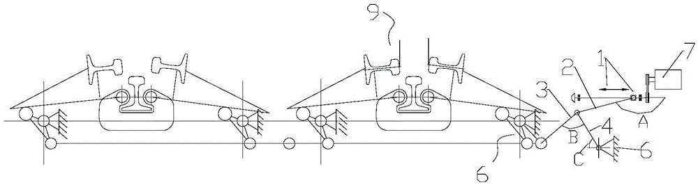
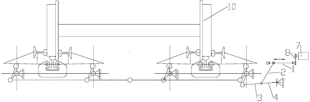
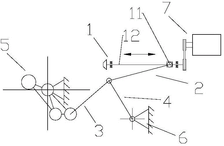
[0055] Such as Figure 1-Figure 8 , showing the ball screw mechanism 1, the initial connecting rod 2, the front connecting rod 3, the rear connecting rod 4, the crankshaft 5, the support seat 6, the motor 7, the belt transmission mechanism 8, the vehicle brake caliper group 9, the wheel 10, wherein the ball screw mechanism 1 has a slider 11 and a screw rod 12, the starting connecting rod 2 is a transmission connecting rod, the supporting base 6 includes a base, and the supporting base 6 also includes a mounting base for a translation mechanism. The structure of the bell crank 5 is like the structure of the bell crank 3 shown in Chinese patent ZL200420009399.1, which is a structure of the prior art.

[0056] The method for realizing deceleration and braking of rail electric vehicles in the present invention includes setting a base, an inner brake caliper and an outer brake caliper, and a motor. The conne...


PUM


Abstract

The invention discloses a method for realizing decelerating brake of a rail electric vehicle. The method comprises a step of arranging a pedestal, vehicle inner and outer brake calipers, a motor, a big crankshaft and a link transmission mechanism, and also comprises the following steps: (1) flexibly connecting the motor with a translation mechanism to convert the rotation of the motor into linear motion, pushing the link transmission mechanism through the translation mechanism via a transmission link to relieve and brake wheels of the rail electric vehicle; (2) meanwhile moving the transmission link under pushing of the translation mechanism to realize an effect of increasing thrust to naturally slow down a brake end point, and acting most of impact force stressed on the transmission link on the translation mechanism and a mounting seat thereof when the transmission link is close to or at the brake end point. The invention also discloses an electric vehicle decelerator device and application of the lead screw transmission mechanism. The brake process is stable, inadequate brake caused by kinematic accumulative error can be effectively avoided, the impact and the vibration to the motor are effectively reduced, a motor shaft is protected, and the brake precision is improved.

Description

technical field [0001] The invention relates to the technical field of a rail electric vehicle reducer, in particular to a method for decelerating and braking an electric vehicle, a device thereof, and an application technology of a screw drive mechanism. Background technique [0002] The structure of the existing electric vehicle reducer on the railway or subway is generally composed of internal and external brake calipers, bearings, motors, multi-link transmission mechanisms, etc., and some products also include floating rails and brake rails. . In the past, this kind of electric reducer has always had some difficult problems that are difficult to overcome but may endanger driving safety: [0003] 1) When the reducer is braked or relieved in place, the motor shaft brakes suddenly, and the torsional stress of the motor shaft cannot meet the repeated impact and is easily deformed or twisted. [0004] 2) When the vehicle reducer is braking or releasing, the m...

Claims


Application Information

Patent Timeline
Patent Type & Authority Applications(China)
IPC IPC(8): B61H13/20B60T13/74
CPCB60T13/746B61H13/20
Inventor 罗海华腾家臻
Owner FOSHAN ANJIELUN TECH CO LTD
Why Eureka
Try Eureka