Powdery material spraying pump

A technology of powder materials and jet pump, which is applied in the direction of conveying bulk materials, conveyors, transportation and packaging, etc., can solve the problems of legacy materials, harsh working environment, affecting the use efficiency, etc., to achieve low system cost and operating cost, and improve Material conveying capacity, the effect of improving processing capacity

Inactive Publication Date: 2015-07-29
ZHENGZHOU DONGDING DRYING EQUIP
View PDF19 Cites 7 Cited by
  • Summary
  • Abstract
  • Description
  • Claims
  • Application Information

AI Technical Summary

Problems solved by technology

[0002] In the field of pneumatic conveying, the current technology mostly uses a material-sealed pump to enter the material, and the material is started and accelerated with a suitable material-gas ratio. During the operation of this device, the movement between the moving parts and the body will be very fast. Wear and tear, the seal will also fail quickly, and it is easy to cause air leakage. Air leakage will bring dust, resulting in a bad working environment and affecting the physical and mental health of the operator; inside the material-sealed pump, the shape and volume of the container, the size of the nozzle The size design is not ideal, and leftover materials will be generated, and the leftover materials will accumulate more and more, and they must be cleaned up after a period of work, otherwise it will affect the efficiency of use, and even the entire system will not work
Due to the above defects, the application field of pneumatic conveying is limited, so a new type of device is urgently needed to replace this product

Method used


Image

  • Powdery material spraying pump
  • Powdery material spraying pump

Examples


Embodiment 1

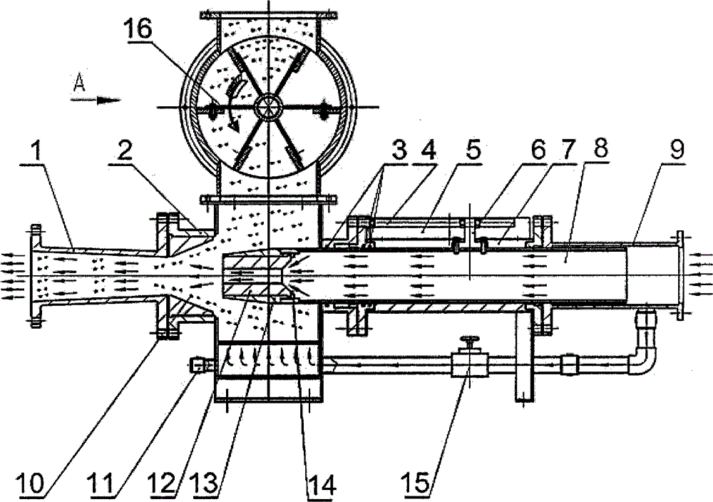
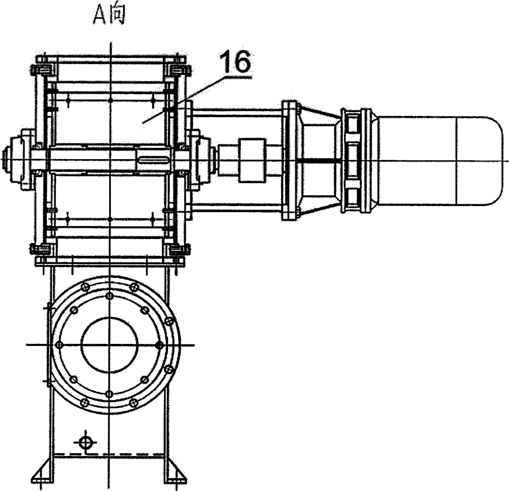
[0021] Such as figure 1 and figure 2 Shown, a kind of powdery material injection pump, it comprises air inlet pipe 9, hollow pipe 8, pump body 2, air locker 16, regulating valve 15, and the output port of described air inlet pipe 9 is communicated with hollow pipe 8, so One end of the hollow tube 8 is connected to the intake pipe 9, the other end of the hollow tube 8 is connected to the nozzle 12, the hollow tube 8 is fixedly provided with a slide iron 6, and one end of the slide iron 6 is fixedly arranged on the On the hollow tube 8, the other end of the sliding iron 6 is sleeved on the screw mandrel 4, and the sliding iron 6 and the screw mandrel 4 are screwed in connection; the described nozzle 12 extends into the inside of the pump body 2 , the air locker 16 is arranged above the pump body 2, one side of the pump body 2 is connected with the nozzle 12, the hollow pipe 8, and the intake pipe 9 in sequence, and the other side of the pump body 2 is connected with The conic...

Embodiment 2

[0026] Such as figure 1 and figure 2 Shown, a kind of powdery material injection pump, it comprises air inlet pipe 9, hollow pipe 8, pump body 2, air locker 16, regulating valve 15, and the output port of described air inlet pipe 9 is communicated with hollow pipe 8, so One end of the hollow tube 8 is connected to the intake pipe 9, the other end of the hollow tube 8 is connected to the nozzle 12, the hollow tube 8 is fixedly provided with a slide iron 6, and one end of the slide iron 6 is fixedly arranged on the On the hollow tube 8, the other end of the sliding iron 6 is sleeved on the screw mandrel 4, and the sliding iron 6 and the screw mandrel 4 are screwed in connection; the described nozzle 12 extends into the inside of the pump body 2 , the air locker 16 is arranged above the pump body 2, one side of the pump body 2 is connected with the nozzle 12, the hollow pipe 8, and the intake pipe 9 in sequence, and the other side of the pump body 2 is connected with The conic...


PUM


Abstract

The invention relates to a powdery material spraying pump, which comprises air inlet pipe, a hollow pipe, a pump body, an air closer and a regulating valve, wherein an output opening of the air inlet pipe is communicated with the hollow pipe, one end of the hollow pipe is connected with the air inlet pipe, the other end of the hollow pipe is connected with a spray nozzle, slide iron is fixedly arranged on the hollow pipe, one end of the slide iron is fixedly arranged on the hollow pipe, the other end of the slide iron is arranged on a lead screw in a sleeving way, and the slide iron and the lead screw are screwed and connected; the spray nozzle extends into the pump body, the air closer is arranged above the pump body, one side of the pump body is sequentially connected with the spray nozzle, the hollow pipe and the air inlet pipe, the other side of the pump body is communicated with a cone pipe, the top of the pump body is communicated with the air closer, and the bottom of the pump body is communicated with an airflow source. The powdery material spraying pump has the advantages that the structure is simple, the operation is reliable, the full sealing is realized, no pollution is caused, the system manufacturing cost is low, the operation cost is low, and the automation degree is high.

Description

technical field [0001] The invention belongs to the technical field of pneumatic conveying, and relates to a pneumatic conveying material injection device, in particular to a powder material injection pump. Background technique [0002] In the field of pneumatic conveying, the current technology mostly uses a material-sealed pump to enter the material, and the material is started and accelerated with a suitable material-gas ratio. During the operation of this device, the movement between the moving parts and the body will be very fast. Wear and tear, the seal will also fail quickly, and it is easy to cause air leakage. Air leakage will bring dust, resulting in a bad working environment and affecting the physical and mental health of the operator; inside the material-sealed pump, the shape and volume of the container, the size of the nozzle The size design is not ideal, and leftover materials will be generated, and the leftover materials will accumulate more and more. They mu...

Claims


Application Information

Patent Timeline
Patent Type & Authority Applications(China)
IPC IPC(8): B65G53/50
Inventor 鄢雪丽魏明旺杨文正李理彭占胜
Owner ZHENGZHOU DONGDING DRYING EQUIP
Why Eureka
Try Eureka