Heating energy-saving system with increased capacity and heat

An energy-saving system and heat pump technology, applied in heating systems, household heating, space heating and ventilation details, etc., can solve problems such as limited space for water supply temperature increase, no improvement of haze weather conditions, and unfavorable living environment for residents, etc. To achieve the effect of improving the transmission capacity of the heating network, improving the heating capacity and flexible layout

Pending Publication Date: 2018-06-08
辉宏技术有限公司
View PDF1 Cites 0 Cited by
  • Summary
  • Abstract
  • Description
  • Claims
  • Application Information

AI Technical Summary

Problems solved by technology

Among them, it is very easy to achieve from the perspective of increasing the water supply temperature of the primary network. It only needs to add a steam-water heat exchanger or a peak-shaving boiler in the first station of the thermal power plant. However, considering the following factors, this direction cannot fully complete the expansion needs
[0004] (1) Limited to the limit of the maximum temperature of the heating network, the room for increasing the water supply temperature is limited;
[0005] (2) Increasing the water supply temperature will additionally increase the heat exchange load of the secondary heat exchange station that does not need to be expanded, resulting in excessively high heating temperatures in the corresponding districts and parks, resulting in energy waste
The conversion of coal to gas, commonly known as "coal to gas", can reduce the emission of harmful pollutants to a certain extent, but "coal to gas" has been implemented for many years and has not improved the situation of smoggy weather
In particular, the secondary heat exchange station is basically built close to the residential area, which is also a potential source of smog to a certain extent, which is not conducive to the improvement of the living environment of residents
Therefore, in terms of environmental protection, it is not recommended to use gas-fired peak-shaving boilers to solve the problem of heat increase and expansion. It is also a potential source of smog, which is not conducive to the improvement of residents' living environment.

Method used


Image

  • Heating energy-saving system with increased capacity and heat

Examples


Embodiment Construction

[0020] In order to understand the technical solution of the present invention more clearly, the present invention will be further described below in conjunction with the accompanying drawings.

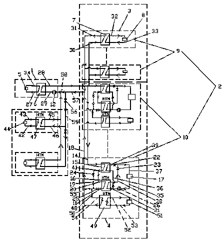
[0021] like figure 1 A capacity-increasing and heat-increasing energy-saving heating system shown includes: a heat exchange primary network 1 and a heat exchange secondary network 2;

[0022] The heat exchange primary network 1 includes a boiler 5, a heat supply pipeline 34, a water return pipe 27, a primary heat exchange station 6, a primary network water supply pipeline 28 and a primary network return water pipeline 29, and the boiler 5 passes through the heat supply pipeline 34, The return water pipe 27 is connected to the primary heat exchange station 6 to form a circulating heat supply. The primary network return water pipeline 29 is connected to the primary network water supply pipeline 28 through the primary heat exchange station 6. The primary network water supply pipeline 28 i...


PUM


Abstract

The invention discloses a heating energy-saving system with increased capacity and heat. When the actual heating area is larger than the originally-designed heating area, the system adopts the technical scheme that a first-stage heat exchange station and a second-stage heat exchange station are internally and respectively added with a cold-heat double-effect energy-saving heat pump to achieve thepurpose of increasing heat and capacity. The heating energy-saving system with increased capacity and heat disclosed by the invention has the beneficial effects that the heat transferring capability of a primary network is fully utilized, the structure is simple, the investment is less, the layout is flexible, the construction period is short, the problem of huge investment of pipe network re-laying is solved, the problem of environmental pollution caused by addition of a peak regulating boiler is also avoided, and the heating energy-saving system is an integrated energy-saving application which can be in more conformity to the policy 'switching from coal to electricity' advocated by the government; the temperature difference of supplied water and returned water of the primary network is larger, and the transferring-capability utilization rate for the original network is higher.

Description

technical field [0001] The invention relates to energy development and utilization technology, in particular to a capacity-increasing and heat-increasing energy-saving heating system. Background technique [0002] At present, in the design and planning of heating pipelines, the speed of urban development is not expected enough, and the heating area covered by some secondary heat exchange stations has greatly exceeded the originally designed heating area. Although the transmission capacity of each secondary pipe network can still meet the requirements, due to various other reasons, it poses a huge challenge to the operation of each secondary heat exchange station. At present, it is impossible to normally guarantee the heating needs of residents in the coldest days, and solutions for heating and capacity expansion are urgently needed. [0003] Considering that the heat transported by the pipe network is proportional to the "flow rate" and the "temperature difference between s...

Claims


Application Information

Patent Timeline
Patent Type & Authority Applications(China)
IPC IPC(8): F24D19/10F24D19/00
CPCF24D19/1009F24D19/0009
Inventor 朱昌辉
Owner 辉宏技术有限公司
Why Eureka
Try Eureka