Rotating lifting appliance for crane

A technology for rotating spreaders and cranes, which is applied in the direction of cranes, load blocks, load hanging components, etc. It can solve the problems that the hook cannot provide a sufficiently stable binding method, the operation tool is dangerous, and the waste of manpower is sufficient to achieve full reliability. Effects of reducing labor burden and increasing safety in use

Inactive Publication Date: 2015-07-29
四川川起起重设备有限公司
View PDF7 Cites 7 Cited by
  • Summary
  • Abstract
  • Description
  • Claims
  • Application Information

AI Technical Summary

Problems solved by technology

[0002] In the crane spreader, the hook is the most commonly used, but when lifting the bar in the steel mill, especially when the length of the bar is long, the hook cannot provide a stable enough binding method; moreover, the bar It is often necess

Method used


Image

  • Rotating lifting appliance for crane
  • Rotating lifting appliance for crane
  • Rotating lifting appliance for crane

Examples


Embodiment Construction

[0014] The present invention will be further described below in conjunction with the drawings:

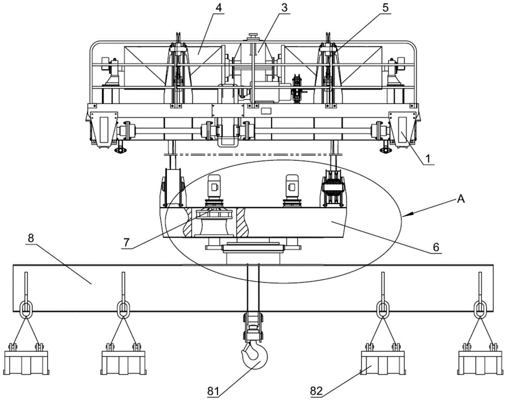
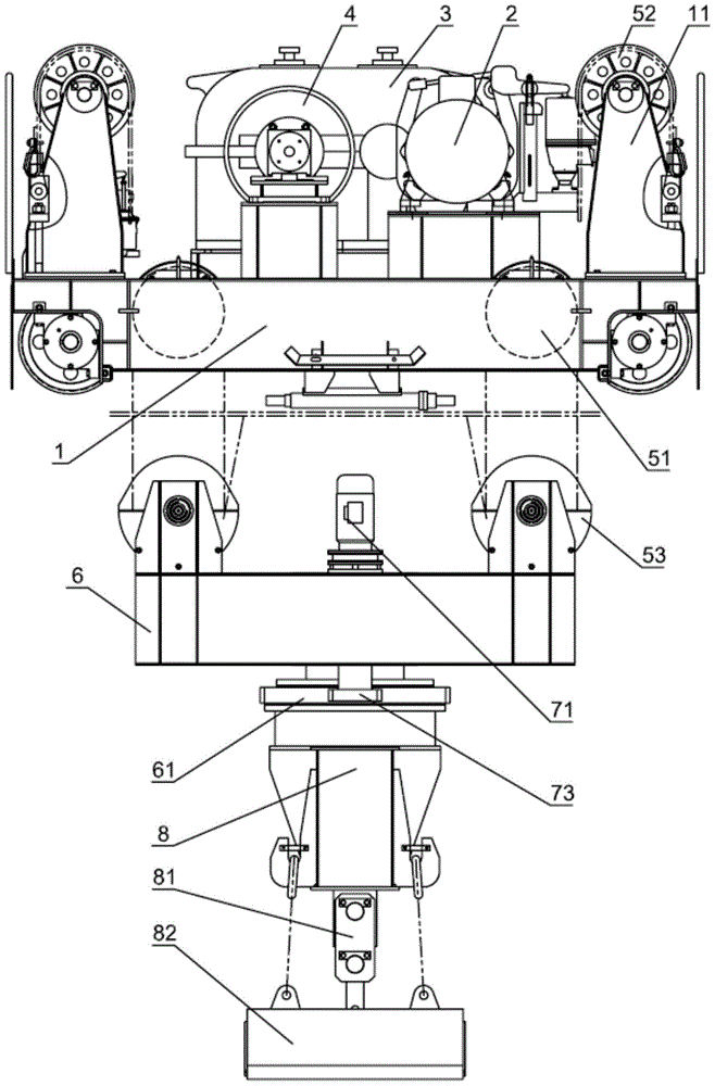
[0015] The invention provides a crane rotating sling, such as attached figure 1 And Figure 4 As shown, it includes a trolley body 1, a lifting drive motor 2, a reduction box 3, two sets of double drums 4, four groups of lifting components 5, a lifting beam 6 and a rotating lifting beam 8. The reduction box 3 is driven by the lifting motor 2 Drive, the double drum 4 is symmetrically arranged on both sides of the reduction box 3 and is fixedly connected with the drive shaft of the reduction box 3. Each double drum 4 contains two steel wires 41, and each double drum 4 passes through the Two steel ropes 41 are connected with two sets of lifting assemblies 5. As attached figure 2 And image 3 As shown, each group of lifting components 5 includes a first fixed pulley 51, a second fixed pulley 52, and a movable pulley 53, the edge of the trolley body 1 is fixedly connected to a support fr...


PUM


Abstract

The invention discloses a rotating lifting appliance for a crane. The rotating lifting appliance comprises a trolley body, a lifting drive motor, a reduction gearbox, two groups of duplex winding drums, four groups of lifting components, a lifting hanging beam and a rotating hanging beam, wherein each of the two groups of duplex winding drums is connected with the corresponding two groups of lifting components; each group of lifting component comprises a first fixed pulley, a second fixed pulley and a movable pulley; the four groups of lifting components form a statically indeterminate structure, so that shake produced by the lifting appliance during the using process can be reduced; a slewing bearing is arranged between the lifting hanging beam and the rotating hanging beam; the lifting hanging beam is fixedly connected with an inner ring of the slewing bearing; the rotating hanging beam is fixedly connected with an outer gear ring of the slewing bearing; a rotating component is fixedly connected onto the lifting hanging beam and is used for driving the outer gear ring of the slewing bearing, so as to reduce the manpower burden and improve the use safety of the lifting appliance. A lifting hook is rotatably connected to the middle position of the lower surface of the rotating hanging beam, a plurality of magnetic lifting appliances are symmetrically distributed on the rotating hanging beam on the two sides of the lifting hook, so that sufficient reliability is provided for the lifting work of bar materials.

Description

Technical field [0001] The invention belongs to the technical field of cranes, and specifically relates to a crane rotating sling. Background technique [0002] Among crane spreaders, hooks are most commonly used, but when lifting bars in steel mills, especially when the length of bars is long, hooks cannot provide a sufficiently stable binding method; furthermore, bars It is often necessary to rotate during transportation. At present, most cases rely on the operator to push and pull the bar to achieve the rotation of the bar. This method of use is wasteful of manpower and potentially dangerous to operating tools. Summary of the invention [0003] In view of the above-mentioned shortcomings in the prior art, the present invention provides a crane rotating spreader. [0004] In order to achieve the above objectives, the solution adopted by the present invention is: a crane rotating spreader, including a trolley body, a lifting drive motor, a reduction box, two sets of double drums, ...

Claims


Application Information

Patent Timeline
IPC IPC(8): B66C11/08B66C11/16B66C13/06
CPCB66C11/08B66C11/16B66C13/06B66C2700/012
Inventor 李长春
Owner 四川川起起重设备有限公司
Why Eureka
Try Eureka