Bearing cage

A cage and bearing technology, applied to bearings, bearing components, roller bearings, etc., can solve the problems of shortened service life, high temperature deformation, and easy noise of the cage, and achieve the effect of improving connection strength and avoiding deformation

Active Publication Date: 2017-07-04
CHANGZHOU CRONOS SPECIAL BEARING MFG
View PDF10 Cites 1 Cited by
  • Summary
  • Abstract
  • Description
  • Claims
  • Application Information

AI Technical Summary

Problems solved by technology

[0003] At that time, when this kind of cage was working, with the high-speed rotation of the rollers, it was easy to generate noise and high-temperature deformation on the cage, which affected the running accuracy of the cage and shortened its service life.

Method used


Image

  • Bearing cage
  • Bearing cage
  • Bearing cage

Examples


Embodiment Construction

[0023] The present invention will be further described in conjunction with specific embodiment now. These drawings are simplified schematic diagrams only to illustrate the basic structure of the present invention in a schematic way, so they only show the components relevant to the present invention.

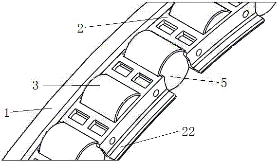
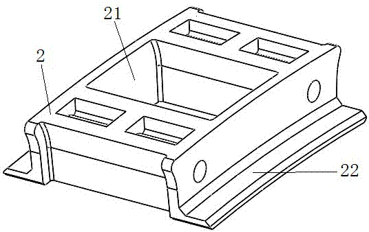
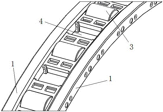
[0024] Such as Figure 1 to Figure 2 As shown, a bearing cage includes two retaining rings 1 arranged symmetrically in the axial direction, and several spacer blocks 2 made of self-lubricating materials are arranged between the two retaining rings 1, and each spacer block 2 is fixedly arranged on two sides. Between the retaining rings 1, and each spacer block 2 forms an annular structure between the two retaining rings 1; a single spacer block 2 is provided with at least one first rolling groove 21, and the first rolling grooves 21 of each spacer block 2 are respectively The first roller 3 is provided, and each spacer block 2 is formed by injection molding with the same mold;

...


PUM


Abstract

The invention relates to a cage for bearings, which comprises two axially symmetrical retaining rings, spacers are arranged between the two retaining rings, and each spacer is fixedly arranged between the two retaining rings; a single spacer is provided with At least one first rolling groove, the first rolling groove of each spacer block is respectively provided with first rollers; there is a gap between the end faces of the adjacent two spacer blocks; the gap is between two adjacent spacer blocks Second rolling grooves are formed between the spacer blocks, and second rollers are respectively arranged in the second rolling grooves formed between the spacer blocks. By arranging the rollers in the self-lubricating rolling grooves, the rollers can still maintain good lubrication performance between the rollers and the spacer after rotating for a long time, so as to avoid the noise generated by the rollers rotating on the cage.

Description

technical field [0001] The invention relates to a cage for a bearing. Background technique [0002] In the cage used in the existing large bearings (diameter greater than 400mm), it includes a cage seat, a cage cover and a roller. The roller is connected between the cage seat and the cage cover. The cage seat, the cage Both the cover and the roller are made of metal material, for example, most of them are currently made of copper alloy. [0003] At that time, when this kind of cage was working, with the high-speed rotation of the rollers, it was easy to generate noise and high-temperature deformation on the cage, which affected the running accuracy of the cage and shortened its service life. Contents of the invention [0004] The technical problem to be solved by the present invention is to provide a cage for bearings by overcoming the deficiencies of the prior art. [0005] The technical solution adopted by the present invention to solve the technical problem is: a cage...

Claims


Application Information

Patent Timeline
Patent Type & Authority Patents(China)
IPC IPC(8): F16C33/46F16C33/66F16C37/00
CPCF16C19/24F16C33/4611F16C33/4664F16C2300/14
Inventor 周军
Owner CHANGZHOU CRONOS SPECIAL BEARING MFG
Why Eureka
Try Eureka