Unidirectional driving mechanism of bike tower base and flower drum main body

A one-way transmission, bicycle technology, applied in one-way clutches, mechanical equipment, clutches, etc., can solve problems such as large resistance and loud noise, and achieve the effect of reducing wear and inertial resistance

Inactive Publication Date: 2015-07-29
何家锋
View PDF6 Cites 0 Cited by
  • Summary
  • Abstract
  • Description
  • Claims
  • Application Information

AI Technical Summary

Problems solved by technology

[0002] In order to realize the power transmission between the freewheel and the main body of the hub, a one-way transmission mechanism is set between the freewheel and the main body of the hub. The one-way transmission mechanism used in the prior art is a ratchet and pawl mechanism. As everyone knows, traditional During the transmission process of the ratchet and pawl mechanism, the pawl is kept radially facing the outer ring gear. When the ratchet and pawl mechanism of this structure is not transmitting power, the pawl is still pushed against the ratchet, resulting in Every time the pawl jumps over a ratchet tooth, it will make a lot of noise. At the same time, because of this reason, when the bicycle is pushed forward or the bicycle is inertial, the resistance between the pawl and the ratchet wheel will be very large. Of course, it will also increase the wear and tear of the pawl and ratchet.

Method used


Image

  • Unidirectional driving mechanism of bike tower base and flower drum main body
  • Unidirectional driving mechanism of bike tower base and flower drum main body
  • Unidirectional driving mechanism of bike tower base and flower drum main body

Examples


Embodiment Construction

[0014] The technology will be further described below in conjunction with the accompanying drawings.

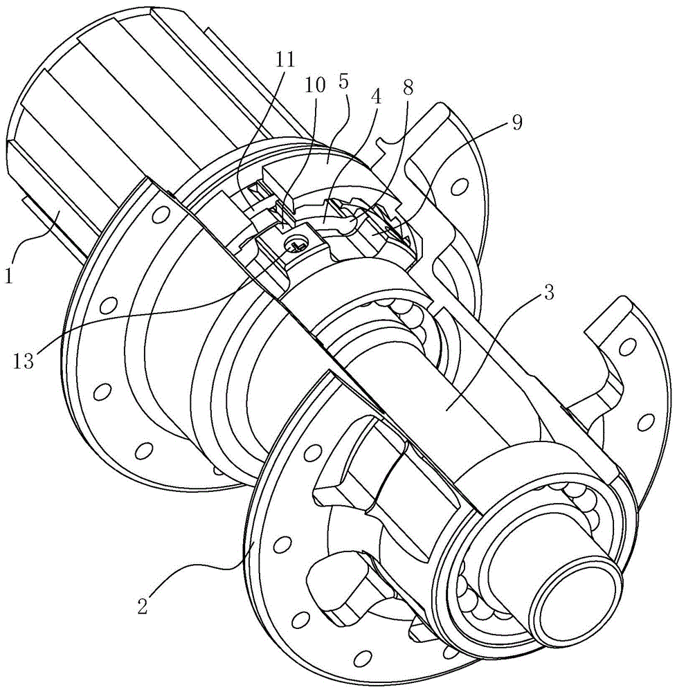
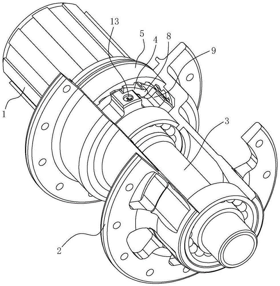
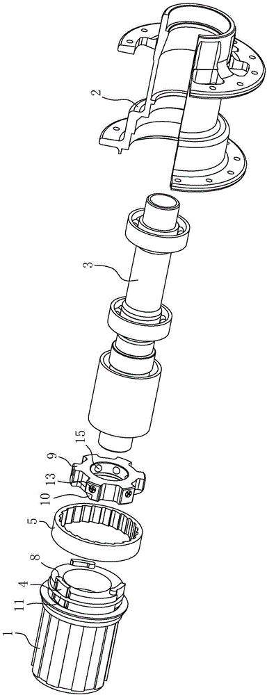
[0015] The one-way transmission mechanism between the freewheel base and the hub main body in this embodiment includes a freewheel base 1, a hub main body 2, a central shaft 3, claws 4, and an inner gear ring 5, and the freewheel base 1 and flower, 2 are passed through the central shaft 3, on the peripheral surface of the freewheel body 1 facing the hub main body 2, there is a first groove 6 that matches the shape of the claw 4, and one end of the first groove 6 is a cylindrical pit 7, The cylindrical pit 7 is a pit less than ninety degrees, and one end of the claw 4 is formed with a cylinder 8, which matches the cylindrical pit 7, and the cylinder 8 is embedded in the cylindrical pit 7, so that The claw 4 is movably bolted on the freewheel 1, and the claw 4 can rotate around its own cylinder 8. A middle ring 9 is arranged between the freewheel 1 and the hub main body 2 on th...


PUM


Abstract

The invention discloses a unidirectional driving mechanism of a bike tower base and a flower drum main body. The unidirectional driving mechanism comprises a tower base, a flower drum main body and a middle shaft, wherein the tower base and the flower drum main body are connected to the middle shaft in a penetrating manner; the circumference of one side, matched with the flower drum main body, on the tower base is provided with a clamping claw; the clamping claw is movably connected to the tower base by a bolt; on the middle shaft, a middle ring is arranged between the tower base and the flower drum main body; a guide bevel is arranged from inside to outside on the outer circumferential surface of the middle ring; a resistance mechanism is arranged between the middle ring and the middle shaft; one segment of the clamping claw is horizontally laid on the guide bevel; a bolt joint point is positioned at the root part of the guide bevel; the tower base is provided with a spring around the tower base; the clamping claw is surpasses and pressed by the spring; an inner gear ring is arranged at the flower drum main body and corresponds to the clamping claw in position; the clamping claw is positioned in the inner gear ring; clamping and separation of the clamping claw and the inner gear ring can be realized by controlling stretching and retraction of the clamping claw; the separation is complete separation, so that sound-free and noise-free effects can be realized during forward pushing and inertia running of a bike, and inertia resistance is reduced.

Description

Technical field: [0001] The invention relates to a one-way transmission mechanism of a bicycle tower base and a hub main body. Background technique: [0002] In order to realize the power transmission between the freewheel and the main body of the hub, a one-way transmission mechanism is set between the freewheel and the main body of the hub. The one-way transmission mechanism used in the prior art is a ratchet and pawl mechanism. As everyone knows, traditional During the transmission process of the ratchet and pawl mechanism, the pawl is kept radially facing the outer ring gear. When the ratchet and pawl mechanism of this structure is not transmitting power, the pawl is still pushed against the ratchet, resulting in Every time the pawl jumps over a ratchet tooth, it will make a lot of noise. At the same time, because of this reason, when the bicycle is pushed forward or the bicycle is inertial, the resistance between the pawl and the ratchet wheel will be very large. Certa...

Claims


Application Information

Patent Timeline
Patent Type & Authority Applications(China)
IPC IPC(8): F16D41/30
Inventor 何家锋
Owner 何家锋
Why Eureka
Try Eureka