Chain sheet joint

A chain piece and outer chain piece technology, applied in the direction of chain elements, belts/chains/gears, mechanical equipment, etc., can solve problems such as unsatisfactory use, danger, obstruction, etc., and achieve the effect of reducing collisions and ensuring safety

Active Publication Date: 2015-07-29
YABAN CHAIN INDAL
View PDF4 Cites 1 Cited by
  • Summary
  • Abstract
  • Description
  • Claims
  • Application Information

AI Technical Summary

Problems solved by technology

[0005] However, after using the previous patent, it was discovered that in order to prevent the chain shaft 97 from directly sliding in parallel and laterally exiting the small diameter portion 94, a plurality of first latching blocks must be provided at the position of the inner edge surface 942. 96, in order to increase the effect of its locking, therefore, the distance 944 between the large diameter portion 93 and the small diameter portion 94 relative to the engaging hole 92 is bound to increase, so when the distance 944 increases, the The length 981 of the circular arc place 98 on the periphery of the outer chain sheet 9 must be reduced, otherwise the outer chain sheet 9 will start to break from the large diameter portion 93 and the edge of the circular arc place 98, but due to the length 981 of the circular arc place 98 The length of the chain shaft 97 is reduced, so when it is meshed with the teeth of the bicycle chainring, it will cause hindrance; The neck portion 972 will move axially, and the height of the fastening portion 971 of the chain shaft 97 will be higher than the blocking surface 943, so that the chain shaft 97 will slide back from the small diameter portion 94 in parallel to the inside the large-diameter portion 93, so that the chain shaft 97 is separated from the outer chain piece 9, and the whole chain is separated, thereby causing danger, so it is not ideal in use.

Method used


Image

  • Chain sheet joint
  • Chain sheet joint
  • Chain sheet joint

Examples


Embodiment Construction

[0036] In order to further explain the technical solution of the present invention, the present invention will be described in detail below through specific examples.

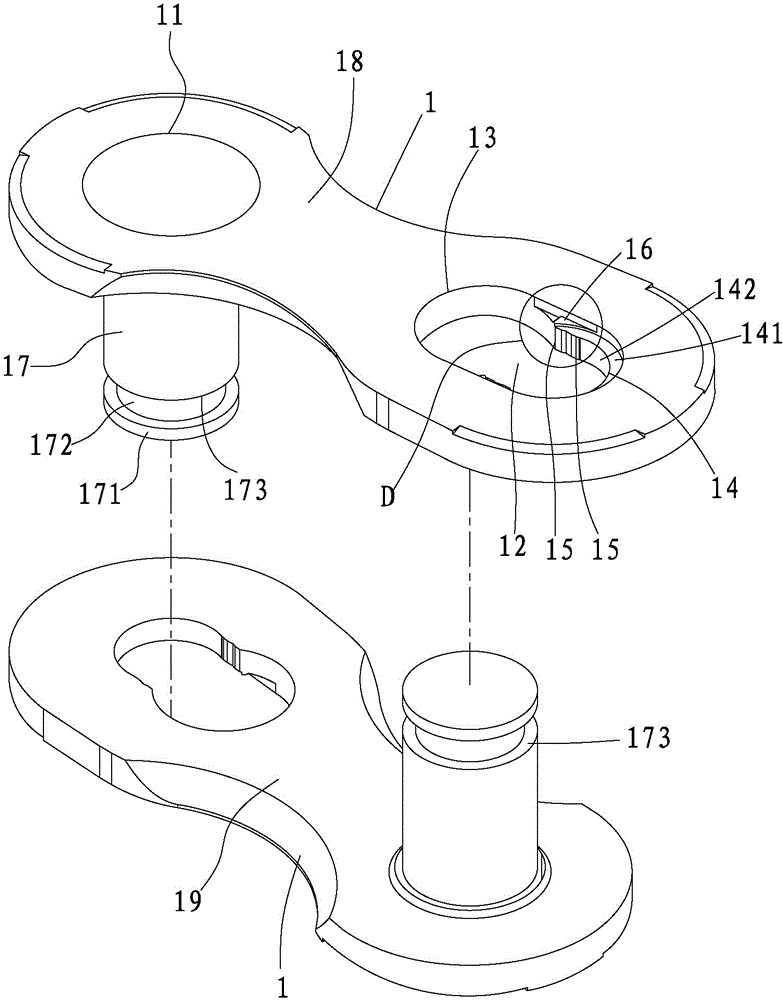
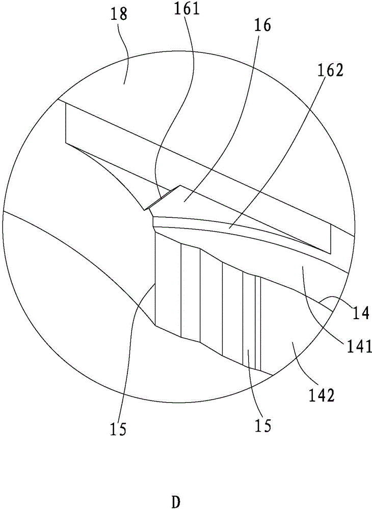
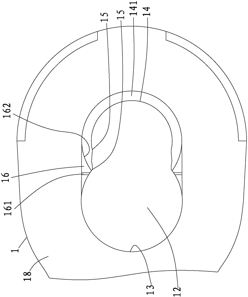
[0037] First, see figure 1 , figure 2 and image 3As shown, the embodiment of the present invention is provided with two opposite outer chain pieces 1, and the two outer chain pieces 1 are respectively provided with a first side 18 and a second side 19, and the outer chain piece 1 is provided with a 18 to the second side 19 through a perforation 11 and an adjacent snap-in hole 12 at an appropriate distance, the snap-in hole 12 is formed with a large-diameter portion 13 and a small-diameter portion 14 intersecting, wherein the periphery of the small-diameter portion 14 is in the The first side 18 is concavely provided with a fastening surface 141, and the small diameter portion 14 is provided with an inner edge surface 142 perpendicular to the fastening surface 141, and the inner edge surface 142 is close to...


PUM


Abstract

The invention discloses a chain sheet joint. The chain sheet joint is that a through hole and a clamping hole are formed in an outer chain sheet, wherein the clamping hole is provided with a large-diameter part and a small-diameter part which are intersected; a buckling surface is concavely arranged around the circumferential edge of the small-diameter part, and an inner edge surface vertically connected with the circumferential edge of the small-diameter part is arranged to the circumferential edge of the small-diameter part; a clamping block and a stopping block are arranged on the inner edge surface; an inclined surface is arranged in the stopping block, adjacent to the large-diameter part, and while a resisting surface is arranged adjacent to the small-diameter part; a hinge shaft is fixed into the through hole; a buckling part is arranged at one end of the chain shaft, and a small-diameter neck part is continuously connected to one end of the chain shaft; an end surface is formed on the hinge shaft, adjacent to the neck part; a deformation gap which is not more than the height of the stopping block is formed between the end surface and another oppositely-assembled outer chain sheet. With the adoption of the chain sheet joint, the chain shaft cannot be separated from the outer chain sheet, so that the safety of a chain in use can be ensured.

Description

technical field [0001] The present invention relates to a link joint, in particular to a fastening part that can be locked on the chain shaft of another outer link by means of a stopper, so that after the two outer links are plugged and fixed, the inner, outer Link joint structure in which the outer link does not come off easily. Background technique [0002] At present, the common chain structure is mainly provided with two chain rollers and two chain shafts between two inner chain pieces and two outer chain pieces respectively to form a chain structure, so that the inner chain piece and the adjacent outer chain piece There must be a gap between them, so in the process of transmission, the relative movement between the chain shaft and the outer chain piece is easy to occur. Once the chain shaft changes speed, an axial tension will be generated, so that the buckle part of the chain shaft will protrude from the Outside the outer chain piece, the chain shaft will fall off due...

Claims


Application Information

Patent Timeline
Patent Type & Authority Applications(China)
IPC IPC(8): F16G15/10
CPCF16G15/10
Inventor 王文滨
Owner YABAN CHAIN INDAL
Why Eureka
Try Eureka