Energy-saving drying machine used in chemical production
A chemical production and dryer technology, applied in dryers, drying solid materials, drying chambers/containers, etc., can solve the problems of high energy consumption and low work efficiency, achieve uniform material distribution, save energy, and save operation time Effect
- Summary
- Abstract
- Description
- Claims
- Application Information
AI Technical Summary
Problems solved by technology
Method used
Image

Examples
Embodiment Construction
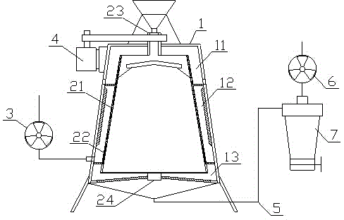
[0016] refer to figure 1 , an energy-saving drying machine used in chemical production, comprising a drying box 1, a drying barrel 2, a dehumidification fan 3, a driving device 4, a material suction pipe 5, a material suction fan 6, and a cyclone separator 7.
[0017] There is a first partition and a second partition in the drying box 1, and the first partition and the second partition divide the drying box 1 from top to bottom into a dehydration box 11, a drying box 12 and a receiving box 13, and the dehydration box 11 , the drying box 12 and the receiving box 13 communicate with each other through the first opening on the first dividing plate and the second opening on the second dividing plate, and some heaters 14 are arranged on the inner wall of the drying box 12, and the bottom of the receiving box There is a discharge port, and a material receiving funnel is arranged below the drying box 1, and the outlet of the material receiving funnel is communicated with the inle...
PUM
 Abstract
Description
Claims
Application Information
 - Generate Ideas
- Intellectual Property
- Life Sciences
- Materials
- Tech Scout
- Unparalleled Data Quality
- Higher Quality Content
- 60% Fewer Hallucinations
Browse by: Latest US Patents, China's latest patents, Technical Efficacy Thesaurus, Application Domain, Technology Topic, Popular Technical Reports.
© 2025 PatSnap. All rights reserved.Legal|Privacy policy|Modern Slavery Act Transparency Statement|Sitemap|About US| Contact US: help@patsnap.com