

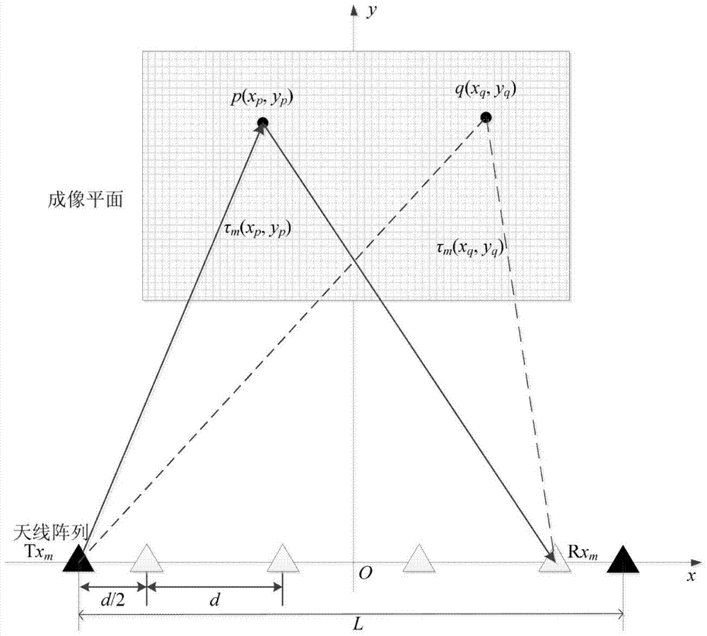
A Suppression Method of Azimuth Grating Lobe in UWB Radar Imaging
An ultra-wideband radar, azimuth technology, applied in the direction of reflection/re-radiation of radio waves, use of re-radiation, measurement devices, etc. Effect
- Summary
- Abstract
- Description
- Claims
- Application Information
AI Technical Summary
Problems solved by technology
Method used
Image

Examples
Embodiment Construction
[0040] The present invention will be further described in detail below in conjunction with the accompanying drawings and specific embodiments.
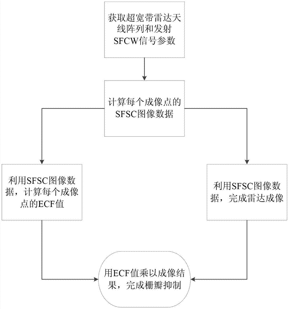
[0041] The method for suppressing the azimuth grating lobes of ultra-wideband radar imaging of the present invention adopts extended coherence factor ECF (Extended Coherence Factor, ECF) weighting to suppress the azimuth grating lobes; , calculate all single-frequency point single-channel image data SFSC (Single FrequencySingle Channel, SFSC); then, coherently sum all single-frequency point single-channel image data SFSC to complete imaging, and use all single-frequency point single-channel image data SFSC to calculate The extended coherence factor ECF of each imaging point; finally, the extended coherence factor ECF is weighted on the imaging results to suppress the azimuth grating lobe of the image and improve the imaging quality.
[0042] For specific applications, see figure 1 and figure 2 , the detailed flow process of the pre...
PUM
 Abstract
Description
Claims
Application Information