

Multi-rotor flight shooting device
A flying shooting, multi-rotor technology, applied in three-dimensional position/channel control and other directions, can solve problems such as difficulty in ensuring the quality of shooting, hitting buildings, and potential safety hazards.
- Summary
- Abstract
- Description
- Claims
- Application Information
AI Technical Summary
Problems solved by technology
Method used
Image

Examples
Embodiment 1
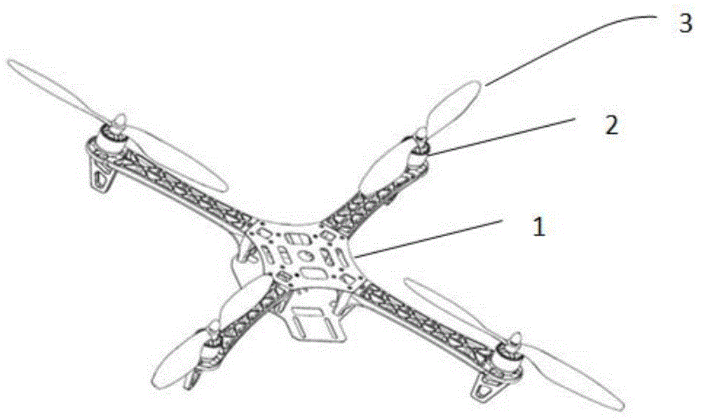
[0062] Such as figure 1 As shown, this embodiment provides a multi-rotor flight shooting device, especially a four-axis rotor flying shooting device, which mainly includes three units: a flight unit, a shooting unit, and a shooting control unit.
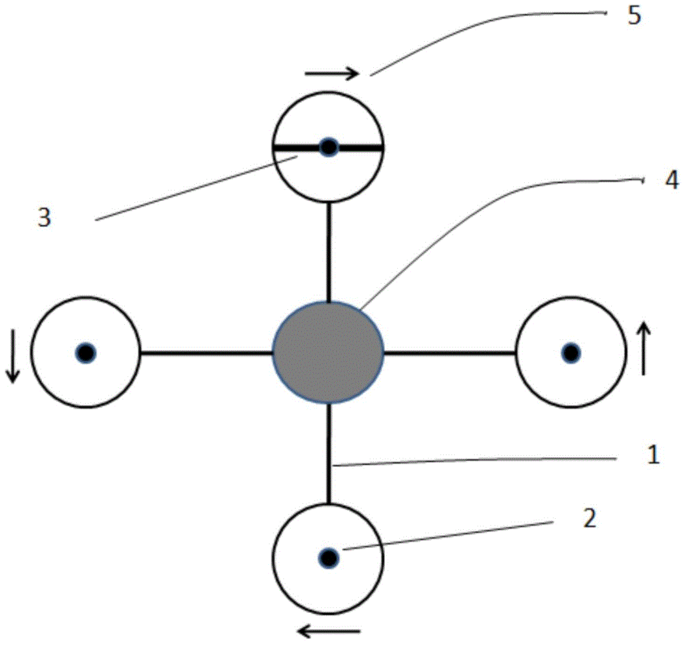
[0063] First, the flight unit of the flight shooting device includes: frame 1 (also called bracket), which is used to provide the rigidity of the entire flight unit and connect other parts of the flight unit; power supply unit, which is used to provide the flight unit The power of the flight controller 4, which can realize the flight trajectory control of the flight unit under the control of external commands, and can also use its own gyroscope and self-balancing circuit design to complete the inertia of the flight unit without external commands. control, to maintain its stable flight state; the number of motors 2 (motors) matches the frame structure, and corresponds to the number of rotors 3, and each motor 2 obtains power support f...
Embodiment 2
[0114] Such as Figure 5 As shown in , which shows several common miniature shooting equipment, the shooting angle of the lens can be adjusted in three dimensions and in a large range. In addition, although the lens adjustment mechanism of the flight shooting device in the first embodiment of the present application is controlled by a programmed circuit, the control structure may also be mechanically controlled.
[0115] Since the focus of this application is to reduce costs and weight, and to achieve targeted solutions to key needs, rather than to solve any immediate needs through program control and intelligent control in a package, the fixed angle, fixed position and fixed The shooting needs of the subject can also be realized through manual adjustment of the lens structure.
[0116] For example, the lens structure of the shooting unit is mechanically connected to the flying unit, which can rotate around the Z axis, X axis or Y axis, and after manually controlling the lens...
Embodiment 3
[0120] The shooting unit can also be connected with the flight unit through the gimbal. The so-called pan-tilt is exactly the supporting device for installing and fixing the shooting unit, which includes a fixed pan-tilt or an electric pan-tilt.
[0121] Compared with the shooting equipment with the angle-adjustable lens, the shooting equipment supported by the fixed pan / tilt can ensure a larger shooting range, better operation feeling and more convenient use. The shooting equipment installed on the fixed platform, its horizontal and pitch angles can be adjusted in a targeted manner. After reaching the best working posture, just lock the adjustment mechanism.
[0122] Compared with the fixed gimbal mentioned above, the motorized gimbal is suitable for realizing intelligent shooting. The position adjustment of the electric pan / tilt is realized by two executive motors, and the motors receive signals from the controller to run and position accurately. Under the action of the co...
PUM
 Abstract
Description
Claims
Application Information