Substrate separation method and device

A technology for a separation method and a separation device, which is applied in the field of separation methods and devices for solar cell substrates, can solve problems such as chip dropping or fragmentation, unfavorable continuous production, etc., and achieve the effects of reducing the fragmentation rate and improving production efficiency

Inactive Publication Date: 2015-07-29
MOTECH SUZHOU NEW ENERGY
View PDF4 Cites 4 Cited by
  • Summary
  • Abstract
  • Description
  • Claims
  • Application Information

AI Technical Summary

Problems solved by technology

[0005] In view of the above-mentioned shortcomings of the prior art, the purpose of the present invention is to provide a substrate separation method and device, which is

Method used


Image

  • Substrate separation method and device
  • Substrate separation method and device
  • Substrate separation method and device

Examples


Example Embodiment

[0047] Example 1

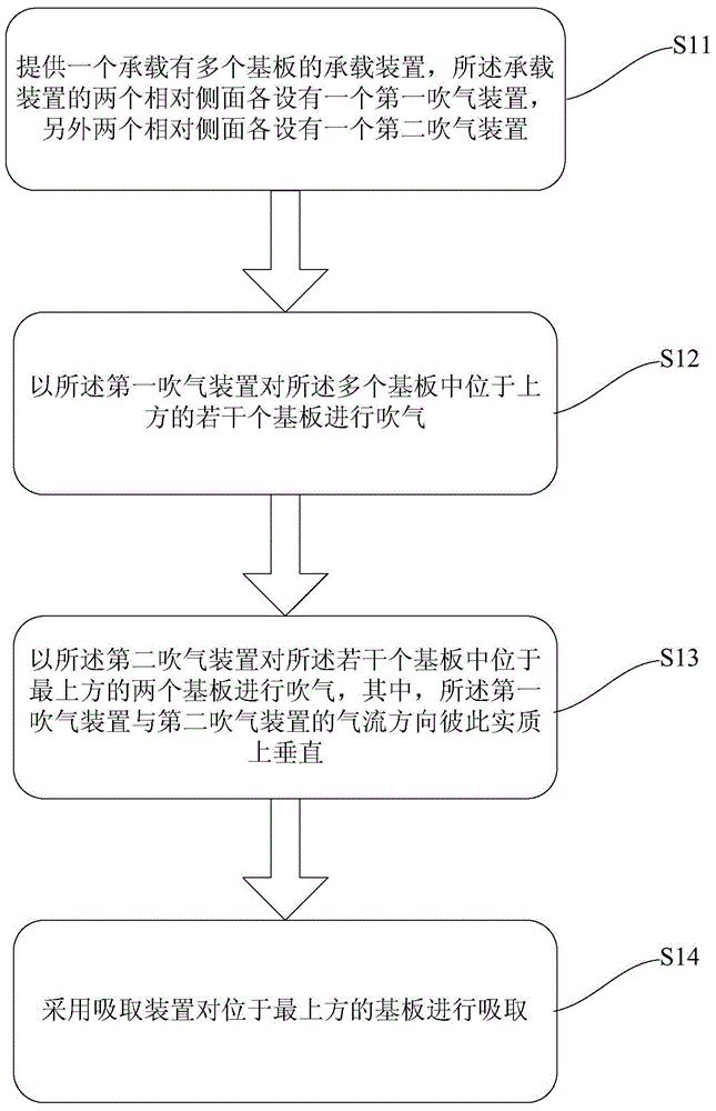
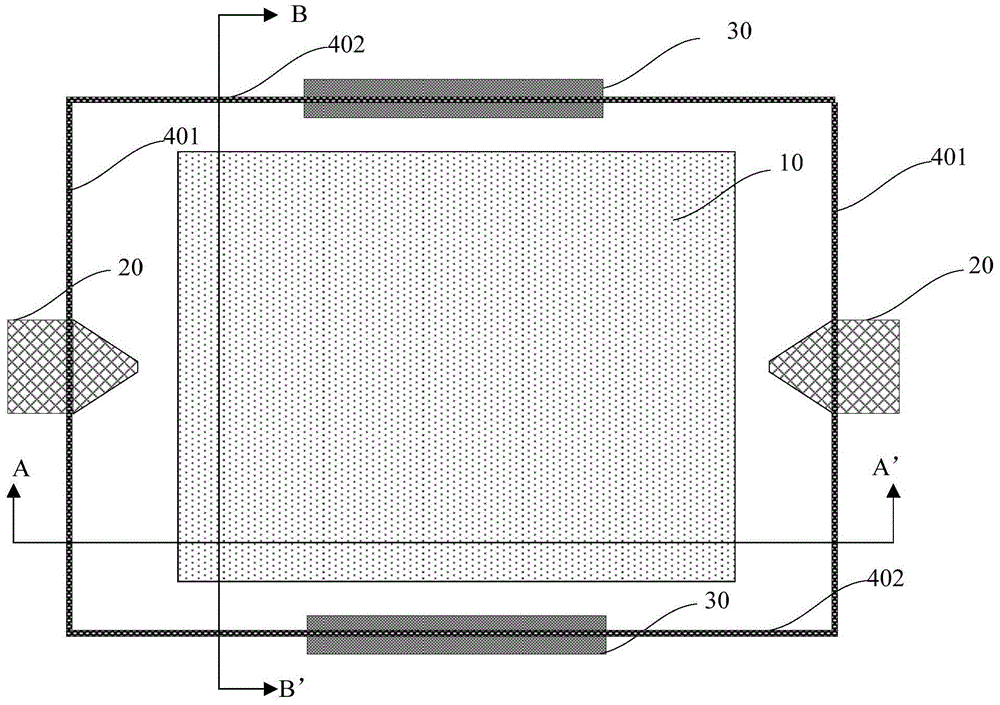
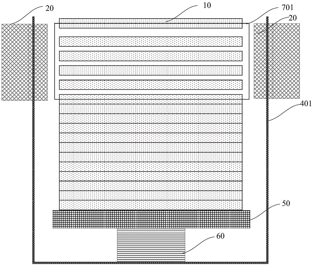
[0048] like Figure 2 to Figure 6 As shown, this embodiment provides a substrate separation device, including:

[0049] A carrying device 50 having two first side surfaces 401 opposite to each other and two second side surfaces 402 opposite to each other;

[0050] a push-up device 60 connected with the carrying device 50 to drive the carrying device 50 to move up and down;

[0051] a suction device (not shown), arranged above the carrying device 50;

[0052] two first air blowing devices 20, respectively disposed on the two first side surfaces 401; and

[0053] The two second air blowing devices 30 are respectively disposed on the two second side surfaces 402, wherein the air flow directions of the first air blowing device 20 and the second air blowing device 30 are substantially perpendicular to each other, that is, it may be At an angle of 90 degrees to each other, or an angle of about 89 degrees or 91 degrees close to the 90-degree angle.

[0054] li...

Example Embodiment

[0069] Example 2

[0070] like Figures 2 to 5 and Figure 7 As shown, this embodiment provides a substrate separation device, the basic structure of which is the same as that of the first embodiment, wherein each of the second air blowing devices 30 has at least one elongated second air outlet 301, and the elongated second air outlet The two air outlets 301 are arranged in a horizontal direction.

[0071] like Figures 1 to 5 and Figure 7 As shown, this embodiment also provides a method for separating substrates, the basic steps of which are the same as those in Embodiment 1, wherein each of the second air blowing devices 30 has at least one elongated second air outlet 301, and the elongated second air outlet The second air outlet holes 301 are arranged in a horizontal direction.

[0072] It should be noted that, in this embodiment, the number of the elongated second air outlet 301 is one, but in other embodiments, the number can be arbitrarily changed according to requ...


PUM


Abstract

The invention provides a substrate separation method and device. The substrate separation method comprises the steps: providing a carrier device bearing a plurality of substrates, wherein two opposite side surfaces of the carrier device are respectively provided with a first blowing device, and the other two opposite side surfaces of the carrier device are respectively provided with a second blowing device; blowing a plurality of upper substrates of the plurality of substrates with the first blowing devices; and blowing the topmost two substrates of the plurality of substrates with the second blowing devices, wherein airflow directions of the first blowing devices and the second blowing devices are actually vertical with each other. According to the separation method and device, by adopting a mode of carrying out pre-separation on silicon wafers, buffer areas and separation areas are formed before absorption, and then, the silicon wafers are sucked up with a sucker disc, thereby effectively reducing fragment rate during absorption and separation, and improving production efficiency.

Description

technical field [0001] The invention belongs to the field of semiconductor manufacturing equipment, and particularly relates to a separation method and device for solar cell substrates. Background technique [0002] A solar cell is a device that directly converts light energy into electrical energy through the photoelectric effect or photochemical effect. Solar cell power generation is a renewable and environmentally friendly power generation method. The power generation process does not produce carbon dioxide and other greenhouse gases, and will not cause pollution to the environment. Because solar cells are clean, non-polluting, inexhaustible, and inexhaustible, they have received more and more attention. At present, solar cells are widely used in daily power generation, transportation, aviation, communication, petroleum, marine and other fields. [0003] In the solar cell production line, the wafer loading end needs to suck and separate the wafers to put them on the autom...

Claims


Application Information

Patent Timeline
IPC IPC(8): H01L21/67
CPCH01L31/1876H01L21/67011
Inventor 陈少华刘起武殷献勇王军朱小琴
Owner MOTECH SUZHOU NEW ENERGY
Why Eureka
Try Eureka