Grinding device for sapphire wafers and grinding method thereof

A sapphire wafer and grinding device technology, which is applied in the direction of grinding devices, grinding machine tools, grinding/polishing equipment, etc., can solve the problems of wafer cracking roughness, grinding quality rate decline, wafer loss, etc., to reduce cracking and roughness exceeding Poor, reduced scratches and chips, reduced abnormal loss

Active Publication Date: 2016-01-06
TUNGHSU GRP
View PDF5 Cites 15 Cited by
  • Summary
  • Abstract
  • Description
  • Claims
  • Application Information

AI Technical Summary

Problems solved by technology

[0002] Sapphire wafer grinding is a very important process in sapphire wafer manufacturing. It determines the TTV, WARP, and surface roughness of sapphire after grinding. In the application of existing technologies, the slurry is generally stirred first, and then poured Put it into the slurry tank, use the way of slurry pump and delivery pipe to transport the slurry to the surface of the grinding disc for supply, and return the ground slurry to the slurry tank for recycling. Actually, in the process of grinding powder configuration In the process, the stirring of the slurry is often very uneven, if it is not completely stirred, the suspension of the grinding slurry is poor, and it is easy to cause wafer cracks and roughness. These chipped and cracked wafer particles will enter the slurry and circulate It will cause the whole bucket of slurry to be used again and be wasted, the surface of the ground wafer will be scratched, and scratches will appear. In serious cases, the entire disk will burst and all the wafers will be lost. In addition, the grinding process The control is not in place, resulting in a decrease in the grinding quality rate and an increase in cost

Method used


Image

  • Grinding device for sapphire wafers and grinding method thereof
  • Grinding device for sapphire wafers and grinding method thereof
  • Grinding device for sapphire wafers and grinding method thereof

Examples


Embodiment Construction

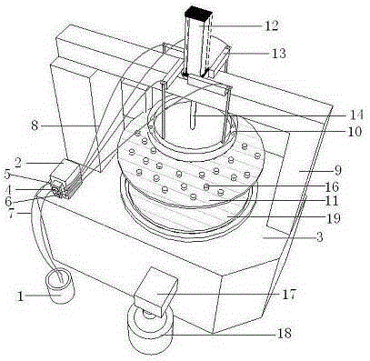
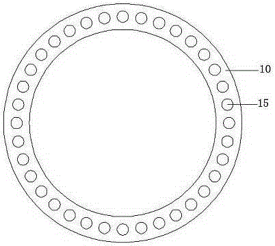
[0028] As shown in the figure, a sapphire wafer grinding device is characterized by comprising a slurry tank 1, a peristaltic pump 2 and a grinder 3. The peristaltic pump 2 includes two pump heads 4, a delivery tube 5 and a pump outlet tube 6. The pump head 4 controls the delivery of the delivery pipe 5. The delivery pipe 5 and the pump outlet pipe 6 are respectively sleeved with a delivery hose 7 and a pump outlet hose 8. The grinder 3 includes a beam 9, The slurry tank 10, the upper grinding plate 11 and the lower grinding plate 19 are provided with a control cylinder 12 and a hose support 13 on the beam 9. The control cylinder 12 is arranged vertically and includes a cylinder rod 14, the cylinder rod 14 It faces vertically downward and is rotatably connected with the upper grinding plate 11 through a bearing to realize the vertical movement and horizontal rotation of the upper grinding plate 11, and the slurry tank 10 is fixedly arranged above the upper grinding plate 11, Lo...


PUM


Abstract

The invention discloses a grinding device for sapphire wafers. The grinding device for sapphire wafers comprises a pulp stock barrel, a peristaltic pump and a grinder, wherein a pulp stock trough is arranged on the grinder, and pulp stock enters into the grinder through the peristaltic pump and the pulp stock trough. The grinding method for the sapphire wafers comprises the following steps: 1, preparing the pulp stock: putting in raw materials by levels and layers; 2, controlling pulp stock flows: putting pulp stock accurately; 3, correcting the flatness of the surface of a grinding lower plate: repeatedly measuring by using a long gauge, a short gauge and a dial gauge, and correcting; 4, distributing powder on the surface of a grinding plate; and 5, grinding both sides of each wafer: firstly carrying out light pressing grinding. The grinding method provided by the invention is characterized in that raw material ratio of the pulp stock is optimized, the pulp stock supplying flow is more accurate, the conveying is more even, before normal grinding, light pressing grinding is performed firstly, the problem of wafer breakage during a grinding process can be prevented for the greatest possible, the wafer breakage rate is lowered, the merit factor of grinding is improved, the removing rate during grinding is stable, the problems of over grinding and low removing rate cannot be caused, and the efficiency is relatively high.

Description

Technical field [0001] The invention relates to the processing field of sapphire substrate sheets, in particular to a sapphire wafer grinding device and a grinding method thereof. Background technique [0002] Sapphire wafer grinding is a very important process in the manufacture of sapphire wafers. It determines the TTV and WARP after sapphire grinding, as well as the surface roughness. In the application of the existing technology, the slurry is generally stirred and then poured. Into the slurry tank, use a slurry pump and a delivery pipe to transport the slurry to the surface of the grinding plate for supply. The grinded slurry is returned to the slurry tank for recycling. Actually in the grinding powder configuration process In the slurry, the slurry is often stirred unevenly, and the slurry is not completely stirred. The suspension of the polishing slurry is poor. It is easy to cause wafer cracks and excessive roughness. These chipped and broken wafer particles will enter th...

Claims


Application Information

Patent Timeline
Patent Type & Authority Applications(China)
IPC IPC(8): B24B37/08B24B37/04B24B37/34B24B57/02
CPCB24B37/042B24B37/08B24B37/34B24B57/02
Inventor 赵元亚王晨宇王禄宝
Owner TUNGHSU GRP
Why Eureka
Try Eureka