Separately coupled feed-in antenna apparatus

An antenna device and coupling feed technology are applied in the directions of devices, antennas, and antenna devices with additional functions that make antennas work in different frequency bands at the same time. Easy to radiate, good bandwidth and efficiency, improve the effect of low frequency bandwidth

Active Publication Date: 2015-07-29
VIVO MOBILE COMM CO LTD
View PDF4 Cites 10 Cited by
  • Summary
  • Abstract
  • Description
  • Claims
  • Application Information

AI Technical Summary

Problems solved by technology

[0004] As disclosed in the Chinese invention patent (Application No.: 201310038945.8), a coupling-feed antenna device for a mobile terminal adopts a breakpoint method at the bottom edge of the antenna coupling metal frame, which only has a low-frequency coupling unit and a grounded high-frequency The high-frequency parasitic unit, and only the low-frequency coupling unit is close to the coupling metal frame, and the feed point is on the same side as the low-frequency coupling metal arm. It is the same as the way that the antenna directly feeds the side bottom breakpoint of the metal frame, and has the disadvantages of insufficient bandwidth and difficult debugging; The way that the antenna directly feeds the breakpoint on the side of the metal frame also has the disadvantage of seriously degrading the communication quality when it is held in the hand.

Method used


Image

  • Separately coupled feed-in antenna apparatus
  • Separately coupled feed-in antenna apparatus
  • Separately coupled feed-in antenna apparatus

Examples


Embodiment 1

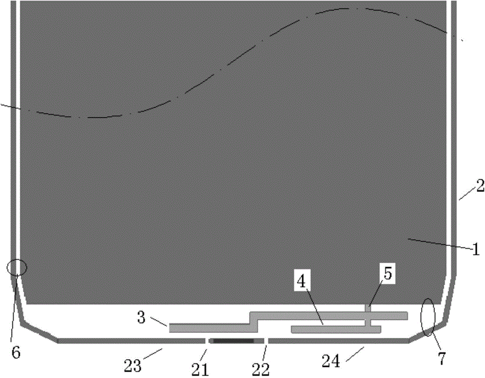
[0026] A kind of separate coupling feed-in antenna device, it comprises a main board or display screen metal support 1, a metal frame 2, and metal frame 2 comprises a short side, and metal frame is provided with first break point 21 and second break point 21 on the short side. Breakpoint 22, a feed pin 5 connected to the RF front end, it also includes:

[0027] A high-frequency metal arm 24 close to the feed pin 5 and a low-frequency metal arm 23 far away from the feed pin are formed by separating the short sides of the metal frame by the first break point 21 and the second break point 22;

[0028] An antenna coupling unit, including a longer low-frequency coupling branch 3 and a shorter high-frequency coupling branch 4 located on the side of the low-frequency coupling branch 3 close to the short side of the metal frame, the end of the low-frequency coupling branch 3 is close to the low-frequency Metal arm 23 , the high frequency coupling branch 4 is close to the high frequenc...


PUM


Abstract

The invention relates to an antenna apparatus, and especially relates to a separately coupled feed-in antenna apparatus. The separately coupled feed-in antenna apparatus comprises a mainboard or a display screen metal support and a metal frame. The metal frame comprises a short edge, and the short edge of the metal frame is provided with at least one break point and at least one feed pin connected with a radiofrequency front end. The separately coupled feed-in antenna apparatus is characterized by further comprising a high-frequency metal arm which is formed by separating the short edge of the metal frame by the break point and is close to the feed pin, and a low-frequency metal arm away from the feed pin; and an antenna coupling unit which comprises a quite long low-frequency coupling branch and a quite short high-frequency coupling branch disposed at one end, close to the short edge of the metal frame, of the low-frequency coupling branch, wherein the tail end of the low-frequency coupling branch is close to the low-frequency metal arm, and the high-frequency coupling branch is close to the high-frequency metal arm. The separately coupled feed-in antenna apparatus has quite good bandwidth and is convenient to debug.

Description

Technical field: [0001] The present invention relates to an antenna device, in particular to an antenna device with separate coupling and feeding. Background technique: [0002] Compared with mobile terminals with ordinary plastic shells, users prefer mobile terminals with metal texture, and the problem of antenna signals caused by this has always been a problem that plagues the industry. [0003] At present, there are three effective solutions: the antenna directly feeds the side breakpoint of the metal frame, the antenna directly feeds the metal frame side bottom breakpoint, and the antenna couples the bottom breakpoint of the metal frame. Each of these solutions has several specific implementations. [0004] As disclosed in the Chinese invention patent (Application No.: 201310038945.8), a coupling-feed antenna device for a mobile terminal adopts a breakpoint method at the bottom edge of the antenna coupling metal frame, which only has a low-frequency coupling unit and a ...

Claims


Application Information

Patent Timeline
Patent Type & Authority Applications(China)
IPC IPC(8): H01Q1/36H01Q1/44H01Q5/307
Inventor 陈玉稳
Owner VIVO MOBILE COMM CO LTD
Why Eureka
Try Eureka