Eureka AIR delivers breakthrough ideas for toughest innovation challenges, trusted by R&D personnel around the world.

Parallel operation circuit for transformers

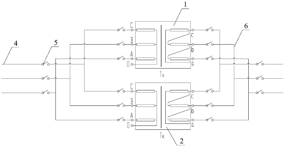
A transformer and parallel connection technology, applied in the field of transformers, can solve the problems of restricting the reuse of old transformers, achieve the effect of small investment, strong practicability, and expanded reuse range

Inactive Publication Date: 2015-07-29
SHANDONG DACHI ELECTRIC
View PDF2 Cites 0 Cited by
  • Summary
  • Abstract
  • Description
  • Claims
  • Application Information

AI Technical Summary

Problems solved by technology

For some areas, the number of substations is relatively small, and it is generally easy to meet the three conditions 1, 2 and 4, but it is often difficult for condition 3
Due to this limitation, many old transformers have impedance voltage per unit values ​​that are not equal to those of current transformers, so they cannot meet the parallel connection requirements, which limits the reuse of old transformers that have not yet expired.

Method used


Image

  • Parallel operation circuit for transformers
  • Parallel operation circuit for transformers
  • Parallel operation circuit for transformers

Examples


Embodiment 1

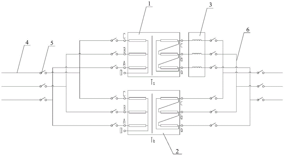
[0024] Such as figure 2 As shown, the parallel circuit of two three-phase double-winding transformers of the present invention includes the existing transformer Ta 1 and the transferred transformer Tb 2. In this embodiment, the impedance voltage per unit value of the transferred transformer Tb 2 is less than the current used one The per unit value of the impedance voltage of transformer Ta 1; set the called transformer Tb 2 in parallel with the current transformer Ta 1, and set the reactor 3 in series on the branch where the called transformer Tb 2 is located, and the reactor 3 is an oil-immersed reactor reactor; preferably, the reactor 3 is arranged on the low-voltage side of the transformer Tb 2 .

[0025] The impedance voltage per unit value of the reactor 3 is equal to the difference between the impedance voltage per unit value of the transformer Ta1 and the impedance voltage per unit value of the transformer Tb2. A magnetic shield is provided at the end of the coil of t...


PUM


Abstract

The invention discloses a parallel operation circuit for transformers, and belongs to the field of transformers. The parallel operation circuit comprises a transformer Ta and a transformer Tb which are parallelly connected on the circuit, an impedance voltage per unit value of the transformer Tb is smaller than that of the transformer Ta, an electric reactor is serially connected on a branch circuit of the transformer Tb, and selection of the electric reactor is further limited. The parallel operation circuit is serially connected with the electric reactor, the impedance voltage per unit values on the parallel operation circuit are equal or closely equal, the parallel operation circuit is reasonable in structure, easy to operate, low in investment and high in practicability, and waste of resources can be effectively avoided, the reuse range of a transformer without service mature is widened, so that the transformer without service mature can be reused, and state-owned resources are greatly saved.

Description

technical field [0001] The invention relates to the field of transformers, in particular to a parallel operation line of two transformers whose impedance voltage per unit value does not match. Background technique [0002] With the development of the power system, the power consumption in some areas has increased rapidly. The original transformer capacity can no longer meet the requirements of power transmission and transformation. It must be withdrawn from operation, and the substation must be upgraded and replaced with a larger capacity or a larger number of transformers. [0003] For the transformers that are about to be out of operation, due to the insufficient estimation of the increase in electricity consumption in the area at the stage of investment construction and program demonstration at that time, the service life of the transformers is far from reaching their expected life; in order to avoid the waste of state-owned assets, such transformers have been maintained. ...

Claims


Application Information

Patent Timeline
IPC IPC(8): H02J3/38
Inventor 董景义贾丙华刘元昌
Owner SHANDONG DACHI ELECTRIC
Why Eureka
Eureka Blog
Learn More