Motor, rotor and method for manufacturing rotor

一种电动机、转子的技术,应用在电动组件、制造定子/转子本体、机电装置等方向,能够解决电动机大型化等问题

Active Publication Date: 2015-07-29
DENSO CORP
View PDF11 Cites 20 Cited by
  • Summary
  • Abstract
  • Description
  • Claims
  • Application Information

AI Technical Summary

Problems solved by technology

In this case, the motor will become larger in the axial direction

Method used


Image

  • Motor, rotor and method for manufacturing rotor
  • Motor, rotor and method for manufacturing rotor
  • Motor, rotor and method for manufacturing rotor

Examples


Embodiment Construction

[0031] below, according to Figure 1 to Figure 4 A first embodiment of the motor will be described.

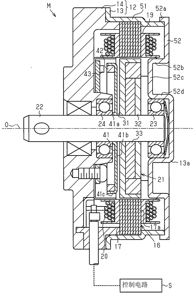
[0032] Such as figure 1 As shown, the housing 12 of the brushless motor M as a motor has: a yoke case 13 formed in a substantially bottomed cylindrical shape; Closed, the end plate 14 is made of a resin material which is a non-magnetic body.

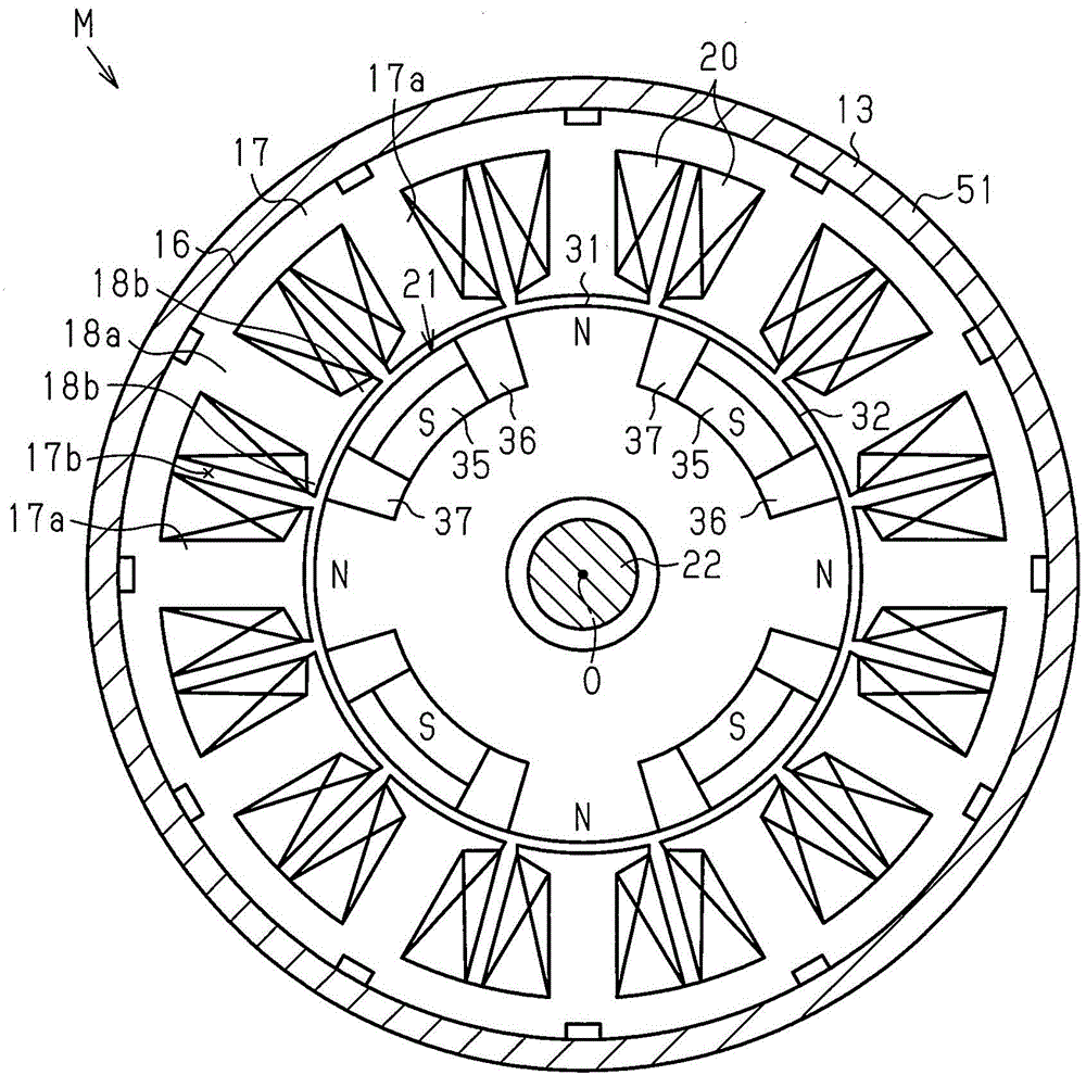
[0033] Such as figure 1 As shown, the stator 16 is fixed to the inner peripheral surface of the yoke housing 13 . The stator 16 includes: a stator core 17 having a plurality of teeth 17 a extending radially inward; and a coil 20 wound around the teeth 17 a of the stator core 17 via an insulator 19 . The stator 16 generates a rotating magnetic field by supplying a driving current from an external control circuit S to the winding 20 .

[0034] Such as figure 2 As shown, the stator core 17 of the first embodiment has twelve teeth 17 a in the circumferential direction. Therefore, the number of tooth spaces 17b formed between each too...


PUM


Abstract

A motor includes a stator, a rotor, and a case. The stator includes a stator core and windings. The rotor is provided inside the stator. The rotor includes first and second rotor cores and a field magnet. The first and second rotor cores each includes a core base and claw-shaped magnetic poles. The core bases are opposed to each other and the claw-shaped magnetic poles of the first and second rotor cores are alternately disposed in a circumferential direction. The field magnet is disposed between the core bases in the axial direction. The field magnet is magnetized in the axial direction so as to cause the claw-shaped magnetic poles of the first rotor core and the second rotor core to function respectively as first magnetic poles and second magnetic poles. At least part of an end part of the case in the axial direction is made of a non-magnetic body.

Description

technical field [0001] The present invention relates to a motor, a rotor, and a method for manufacturing the rotor. Background technique [0002] Conventionally, as described in JP-A-2012-115085 and JP-A-2013-99097, a rotor with a so-called Lundell structure is known as a rotor used in a motor. Such a rotor includes a plurality of rotor cores combined by providing a plurality of claw-shaped magnetic poles in the circumferential direction. In the axial direction, field magnets are arranged between the rotor cores so that the claw-shaped magnetic poles alternately function as different magnetic poles. Also, such a rotor is rotatably provided inside a stator having windings. The rotor and the stator are housed in a casing composed of a bottomed cylindrical yoke case and a cover that closes an opening of the yoke case. [0003] However, in the motor described above, the yoke case (the bottom portion) of the magnet is located on the one end face side in the axial direction of ...

Claims


Application Information

Patent Timeline
Patent Type & Authority Applications(China)
IPC IPC(8): H02K29/00H02K29/06H02K1/24H02K1/27H02K15/03
CPCH02K1/27H02K1/2713H02K1/276H02K5/02H02K5/04H02K29/08Y10T29/49012
Inventor 山田洋次土屋贵宏森田智惠三上晃司横山诚也入江胜
Owner DENSO CORP
Why Eureka
Try Eureka