Inductor and manufacturing method thereof

A manufacturing method and inductor technology, applied in the direction of inductor, inductor/transformer/magnet manufacturing, fixed inductor, etc., can solve problems such as short circuit of inductor

Active Publication Date: 2020-10-09
MURATA MFG CO LTD
View PDF7 Cites 1 Cited by
  • Summary
  • Abstract
  • Description
  • Claims
  • Application Information

AI Technical Summary

Problems solved by technology

[0003] However, in such a production method, in the compression process, the notch of the first preliminary molded body is not sufficiently filled with magnetic powder, and the magnetic powder may remain on the surface of the integrated magnetic body of the first preliminary molded body and the second preliminary molded body. Part of the notch
As a result, the part of the coil other than the part connected to the external terminal is exposed from the magnetic body, and the part of the coil other than the part connected to the external terminal is connected to the external terminal, and a short circuit defect occurs.

Method used


Image

  • Inductor and manufacturing method thereof
  • Inductor and manufacturing method thereof
  • Inductor and manufacturing method thereof

Examples


Embodiment approach 1

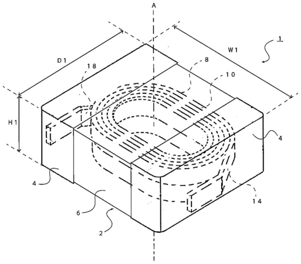
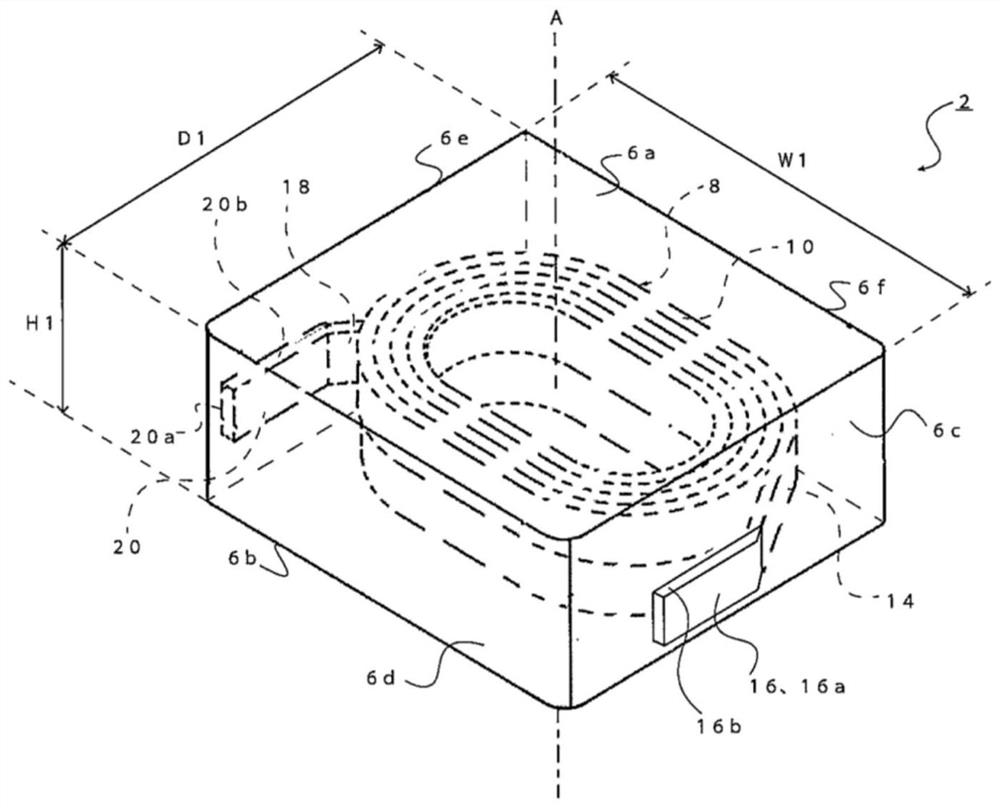
[0038] refer to figure 1 and figure 2 The inductor according to Embodiment 1 of the present invention will be described. figure 1 It is a perspective view which shows the inductor 1 which concerns on Embodiment 1 of this invention. figure 2 yes means figure 1 A perspective view of the body 2 of the inductor 1 is shown.

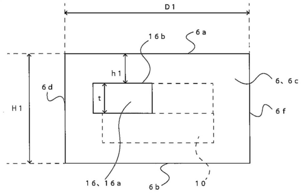
[0039] The inductor 1 includes: a main body 2 including a magnetic body 6 of magnetic powder and a coil 8 embedded in the magnetic body 6 ; and a pair of external terminals 4 formed on the surface of the main body 2 . The magnetic body 6 has a substantially rectangular parallelepiped shape having two opposing main surfaces 6a, 6b and a plurality of (here, four) side surfaces 6c, 6d, 6e, 6f. The coil 8 has a winding portion 10 formed by winding a conductive wire, and a pair of lead-out portions 14 and 18 drawn from the winding portion 10 . At least parts of the lead portions 14 and 18 are exposed from the side surfaces of the magnetic body 6 and are conn...

Embodiment approach 2

[0069] Next, refer to Figure 10 Inductor 101 according to Embodiment 2 will be described. Figure 10 It is a perspective view explaining the coil 108 and the 3rd area|region 30 of the main body 102 of the inductor 101 concerning Embodiment 2 of this invention. Inductor 101 differs from inductor 1 according to Embodiment 1 in that end portions 116 and 120 of a pair of lead portions 114 and 118 are also exposed from one side surface 106 d in the longitudinal direction of magnetic body 106 . Furthermore, the arrangement of the region with a high magnetic powder filling rate is also different from that of the inductor 1 according to the first embodiment. Hereinafter, differences from the inductor 1 according to Embodiment 1 will be described in detail.

[0070] End portions 116 , 120 of lead-out portions 114 , 118 drawn out from winding portion 100 are also exposed on one side surface 106 d in the longitudinal direction of magnetic body 106 . The lead-out parts 114, 118 are be...


PUM

PropertyMeasurementUnit
lengthaaaaaaaaaa
thicknessaaaaaaaaaa
thicknessaaaaaaaaaa

Abstract

The invention provides an inductor and a method for manufacturing the inductor, which can suppress the occurrence of short circuit failure between the external terminal and a part of a coil except forthe part connected with the external terminal. The inductor includes a body including a magnetic body having a coil embedded therein and containing magnetic powder. The coil has a winding portion inwhich a conductive wire is wound around and has a pair of lead portions taken out from the winding portion. The inductor also includes a pair of outer electrodes formed on the body. In the inductor, each of the lead portions is exposed from at least one side surface of the magnetic body and is coupled to a corresponding outer electrode. In addition, with respect to a position at which each of thelead portions is exposed from the at least one side surface of the magnetic body, a magnetic powder content in a region closer to one of the principal surfaces is higher than a magnetic powder contentin a region closer to the other one of the principal surfaces.

Description

technical field [0001] The present invention relates to inductors and methods of manufacturing the same. Background technique [0002] As the miniaturization of electronic equipment progresses, the miniaturization of inductors is also sought. As a miniaturized inductor, there is provided an inductor in which a lead-out portion of a coil arranged in a magnetic body or a terminal electrode portion connected to the lead-out portion is drawn out and exposed on the surface of the magnetic body, and the exposed Some are connected to external terminals. As a method for manufacturing such an inductor, there is a method including the steps of (1) preparing a first preformed body containing magnetic powder having a notch on the side surface and a preformed body containing magnetic powder disposed on the first preformed body. (2) arrange the coil on the first preliminary molded body so that the lead-out part is drawn out of the first preliminary molded body through the notch, (3) arr...

Claims


Application Information

Patent Timeline
Patent Type & Authority Applications(China)
IPC IPC(8): H01F17/04H01F27/255H01F27/28H01F27/29H01F41/02H01F41/061H01F41/076
CPCH01F17/04H01F27/2852H01F27/255H01F27/292H01F41/0246H01F41/061H01F41/076H01F2017/048H01F27/29H01F27/2828H01F17/043H01F27/2823H01F27/327
Inventor 森博康
Owner MURATA MFG CO LTD
Why Eureka
Try Eureka