Centrifugal pendulum damping device

A vibration damping device, vibrator-type technology, applied in spring/shock absorber, vibration suppression adjustment, rotational vibration suppression, etc., can solve the problems of inability to obtain vibration damping performance, and the size of inertial mass body becomes smaller, and achieve vibration damping performance. The effect of boosting and increasing energy absorption

Active Publication Date: 2015-07-29
HONDA MOTOR CO LTD
View PDF10 Cites 5 Cited by
  • Summary
  • Abstract
  • Description
  • Claims
  • Application Information

AI Technical Summary

Problems solved by technology

[0010] The technique described in the above-mentioned Patent Document 1 makes the natural frequency of the inertial mass body constant regardless of the amplitude, thereby improving the vibration damping performance, but it does not solve the problem of interference between the inertial mass bodies caused by the increase in the amplitude, so there are still inertial mass bodies The problem that the size becomes smaller and sufficient damping performance cannot be obtained

Method used


Image

  • Centrifugal pendulum damping device
  • Centrifugal pendulum damping device
  • Centrifugal pendulum damping device

Examples


no. 1 Embodiment approach

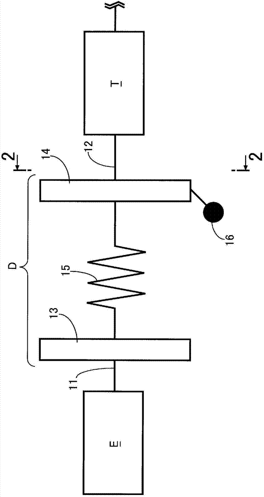
[0036] Such as figure 1 As shown, the damper D is disposed between the crankshaft 11 of the engine E of the automobile and the main shaft 12 of the transmission T. The damper D is configured to have a primary flywheel 13 connected to the crankshaft 11 and a secondary flywheel 14 connected to the main shaft 12. , a plurality of springs 15 connecting the primary flywheel 13 and the secondary flywheel 14 . . . Three inertial mass bodies 16 .

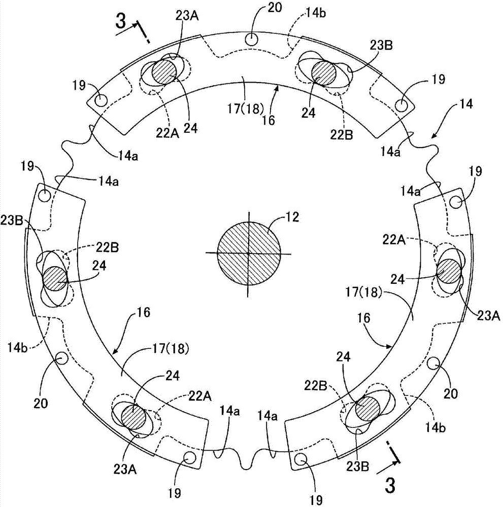
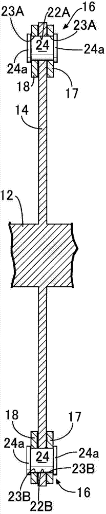
[0037] Such as Figure 2 to Figure 6 As shown, the secondary flywheel 14 is a disk-shaped member centered on the main shaft 12, and supports three fan-shaped inertial mass bodies 16... at intervals of 120° on its outer periphery. The three fan-shaped inertial mass bodies 16 . The first half body 17 and the second half body 18 are in contact with each other at both end portions joined together by two rivets 19, 19, and at the central portion other than the two end portions are formed on the surfaces facing each other. In the recesses 17a...

no. 2 Embodiment approach

[0064] Compared with the first embodiment (refer to Figure 4 ) and the second embodiment (see Figure 7 ) It can be seen that in the first embodiment, the moment of inertia is increased by increasing the wall thickness of the first and second half bodies 17 and 18 at both ends of the inertial mass body 16 away from the center of gravity position G, and in the second embodiment In the method, the wall thicknesses of the first and second half bodies 17, 18 are fixed, and counterweights 25, 25 made of a metal with a large specificity such as tungsten or lead are supported on the rivets 19, 25 at both ends far from the center of gravity position G. 19, thereby increasing the moment of inertia. The weights 25, 25 also function as washers for keeping the distance between the first and second halves 17, 18 constant.

[0065] Also in this second embodiment, the same effect as that of the first embodiment can be achieved.


PUM


Abstract

The centrifugal pendulum damping device is provided with: a support (14), which has pairs of first curved tracks (22A, 22B) and is fixed to a rotating shaft (12); inertial masses (16), which have a pair of second curved tracks (23A, 23B) and are supported on the circumference of the support (14); and pins (24) that are fitted so as to roll freely in the sections where the first curved tracks (22A, 22B) and the second curved tracks (23A, 23B) intersect. Because the shapes of the paired first curved tracks (22A, 22B) are made to differ from each other and the shapes of the paired second curved tracks (23A, 23B) are made to differ from each other, the inertial masses (16) not only undergo translational motion in the circumferential direction of the support (14) but also autorotational motion, thereby improving damping performance for the damping of low frequencies. Moreover, the autorotational motion makes protrusion of the inertial masses (16) from a region (S) of the support (14) difficult and if the size of the inertial masses (16) is increased to that extent, it is possible to further improve damping performance.

Description

technical field [0001] The present invention relates to a centrifugal vibrator type vibration damping device that supports a plurality of inertial mass bodies on a support body that rotates together with a rotating shaft, and vibrates the inertial mass bodies according to the rotational variation of the rotating shaft to exert a vibration damping function. Background technique [0002] Regarding such a centrifugal vibrator type vibration damping device, the following known technology is proposed in the following patent document 1: a pin is fitted in a rolling manner to a pair of first curved tracks provided on a rotating support body and the inertial In the paired second curved track provided on the mass body, and the inertial mass body is vibrated along the arc-shaped trajectory of the radius of curvature, so that the natural vibration frequency of the inertial mass body is always constant regardless of the amplitude, thus Improved vibration damping. [0003] In addition, ...

Claims


Application Information

Patent Timeline
Patent Type & Authority Applications(China)
IPC IPC(8): F16F15/31F16F15/14
CPCF16F15/145F16F15/31
Inventor 西井文哉山本一彦
Owner HONDA MOTOR CO LTD
Why Eureka
Try Eureka