Supporting joint with U-shaped steel plate

A U-shaped, steel plate technology, applied to building components, earthquake resistance, construction, etc., can solve the problems of affecting the function of the structure, large interaction, inconvenient maintenance, etc., and achieve the effect of simple construction, easy operation, and low cost

Active Publication Date: 2015-08-05
ARCHITECTURAL DESIGN & RES INST OF SOUTH CHINA UNIV OF TECH
View PDF6 Cites 0 Cited by
  • Summary
  • Abstract
  • Description
  • Claims
  • Application Information

AI Technical Summary

Problems solved by technology

Due to the direct contact between the main structure and the tower structure, this kind of support has a large interaction. Once it is damaged, it will directly affect the use function of the structure, and it is inconvenient to maintain.

Method used


Image

  • Supporting joint with U-shaped steel plate
  • Supporting joint with U-shaped steel plate
  • Supporting joint with U-shaped steel plate

Examples


Embodiment Construction

[0034] The present invention will be described in further detail below in conjunction with the accompanying drawings, but the embodiments of the present invention are not limited thereto.

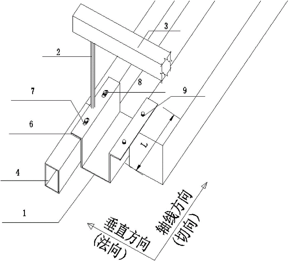
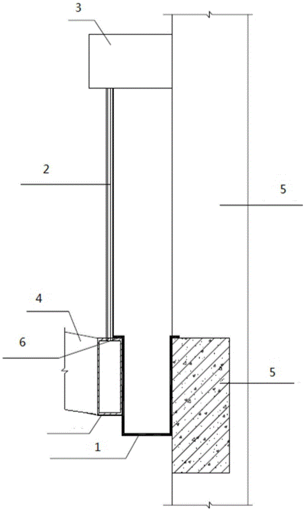
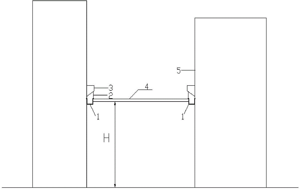
[0035] Such as figure 1 As shown in ‐4, a support node with U-shaped steel plate is mainly composed of U-shaped steel plate 1, backing plate 6, long strip installation hole 7 and suspender 2; the cross section of U-shaped steel plate 1 is U-shaped or groove-shaped , the upper end of the U-shaped or groove-shaped opening is provided with a flange; during installation, one flange is erected on the conjoined structure 4, and the other flange is erected on the multi-tower structure 5; one end of the suspender 2 passes through the U-shaped steel plate 1 The middle part of the flange on one side is connected with the conjoined structure 4, and the other end is connected with the corbel 3 of the multi-tower structure 5; the flange connecting the U-shaped steel plate 1 and the conjoined structure i...


PUM


Abstract

The invention discloses a supporting joint with a U-shaped steel plate. The supporting joint is mainly composed of a U-shaped steel plate, a cushion plate, a long-strip installing hole and a suspender; the cross section of the U-shaped steel plate is in the shape of U or groove, the upper end of the U-shaped or groove-shaped opening is provided with wing edges, wherein one wing edge is overlapped on a connection structure, and the other one wing edge is overlapped on a multi-tower structure; one end of the suspender is crossed through the middle part of the wing edge at one side of the U-shaped steel plate and connected with the connection structure, and the other end is connected with a bracket of the multi-tower structure; a long-strip installing hole is arranged on the wing edge of the U-shaped steel plate connected with the connection structure along the axial direction, and long-strip installing hole is connected with the connection structure through a bolt or an anchor; the wing edge at the other side of the U-shaped steel plate is connected with the multi-tower structure through the bolt or the anchor. The supporting joint with the U-shaped steel plate is simple in structure and convenient to construct; besides, the supporting joint is simple and reasonable in stress, and can be recovered in small shock and repaired in big shock; particularly, the supporting joint plays the functions of 'relative isolation' and 'fuse wire' to the connection structure and the multi-tower structure; besides, the practicability is strong.

Description

technical field [0001] The invention relates to a support node of a steel structure, in particular to a support node with a U-shaped steel plate. Background technique [0002] The main forms of steel structure support nodes are fixed hinge support, movable hinge support and fixed support. The fixed hinge support is a form of support that only transmits axial force and shear force without transmitting bending moment, that is, the horizontal and vertical displacement of the node is limited, but rotation can occur. Fixed hinge supports include pin hinge supports, spherical hinge supports and arc hinge supports. The pin shaft support connects the support base and the rotating part through the pin shaft. The spherical hinge support is made of a steel ball fixed on the transition plate and a hemispherical groove connected to the bottom plate of the support, which can rotate freely in two horizontal directions without linear displacement. The method of the arc hinge support is t...

Claims


Application Information

Patent Timeline
Patent Type & Authority Applications(China)
IPC IPC(8): E04B1/36E04B1/98
Inventor 孙文波郑佳丽周伟坚
Owner ARCHITECTURAL DESIGN & RES INST OF SOUTH CHINA UNIV OF TECH
Why Eureka
Try Eureka