High sealing performance piston

A high-sealing and high-performance technology, used in pistons, piston rings, engine components, etc., can solve problems such as affecting work efficiency, loss of sealing performance, and short service life, to improve work efficiency, prolong service life, and reduce mechanical wear. Effect

Active Publication Date: 2017-11-17
李明领
View PDF1 Cites 0 Cited by
  • Summary
  • Abstract
  • Description
  • Claims
  • Application Information

AI Technical Summary

Problems solved by technology

In the actual working process, although the opening of the sealing gas ring in the previous gas ring groove and the opening of the sealing gas ring in the next gas ring groove are misaligned, the opening of the previous sealing gas ring passes through the protruding part of the piston The opening of the sealing gas ring in the next gas ring groove is still open, and with repeated reciprocating operations, the opening of the sealing gas ring changes from small to large, and the air leakage in series is more serious, and its sealing performance is poor. The service life is short, and the piston and gas ring need to be replaced frequently, which wastes time and labor and affects work efficiency
For this reason, the applicant has also made improvements to this, and applied for a patent No. 00220443.6, a utility model patent for a high-sealed piston, which is to arrange two open air rings in the air ring groove, and the There is an annular liner spring with an opening between it and the gas ring groove. The opening of the liner spring and the openings of the two gas rings are 120° from each other; Therefore, the sealing performance of the piston is improved; however, in the actual working process, due to the impact of the piston, the liner spring and the gas ring inevitably still shift, and finally the openings of the liner spring and the two gas rings overlap. And once it overlaps, it cannot be reset, resulting in a complete loss of its sealing performance

Method used


Image

  • High sealing performance piston
  • High sealing performance piston

Examples


Embodiment Construction

[0010] The present invention will be described in further detail below in conjunction with the accompanying drawings.

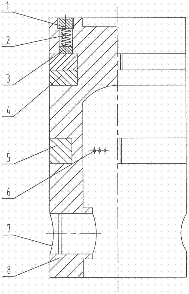
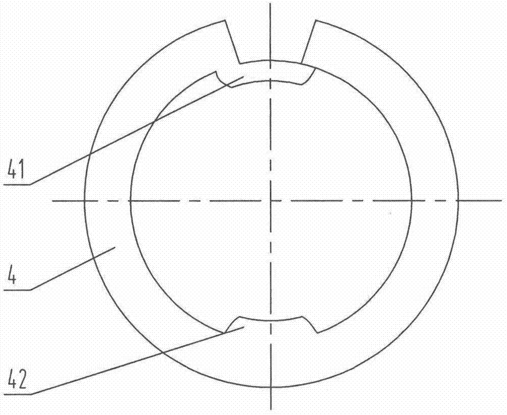
[0011] According to the high sealing performance piston of the present invention, the piston body 8 is provided with a gas ring groove and an oil ring groove from top to bottom; at the bottom of the oil ring groove, two groups of symmetrical ring grooves are arranged, each group of six is ​​connected with the piston body. 8 The oil hole 6 with the inner cavity connected, the oil ring 5 with an opening is arranged in the oil ring groove; two piston pin holes 7 are symmetrically opened on the piston body 8 in the gas ring groove and the lower part of the oil ring groove; There are two sealing gas rings 4 that are arranged in a staggered manner with two openings. The openings of the two sealing gas rings 4 are 180°; One end of the opening is connected; on the inner wall of the sealing gas ring 4 corresponding to the above-mentioned protrusion 41, another same pr...


PUM


Abstract

The invention provides a high-seal-performance piston. An air ring groove and an oil ring groove are formed in a piston body, and an oil ring is arranged in the oil ring groove. Two staggered open sealed air rings are arranged in the air ring groove, and 180-degree openings are formed in the two sealed air rings. Protruding block are arranged on the insides of the openings of the sealed air rings, and the ends of the protruding blocks are connected with the ends of the openings of the sealed air rings. Identical protruding blocks are arranged on the inner walls of the insides of the sealed air rings corresponding to the inner walls of the protruding blocks. Two grooves matched with the two protruding grooves are formed in the bottoms of the air ring grooves. Besides, a plurality of location holes which are uniformly distributed and communicated with the air ring grooves are formed in the top of the piston body along the axial direction. Ejection rods, springs and fixing bolts are arranged in the location holes from the bottom to the top successively. By means of the piston, displacement and air leakage of the sealed air rings are prevented, the seal performance and the work efficiency are improved, the service life is prolonged, the piston is controlled from sucking engine oil from a machine body during the reciprocating inflection point, consumption and pollution of engine oil and fuel are reduce greatly.

Description

technical field [0001] The invention relates to a piston, in particular to a piston with high sealing performance. Background technique [0002] At present, the reciprocating pistons used in various internal combustion engines and compressors are provided with an oil ring groove and two air ring grooves at intervals on the piston body. A single sealing gas ring with an opening, and the openings of the sealing gas rings in the two gas ring grooves are arranged in a misaligned manner. In the actual working process, although the opening of the sealing gas ring in the previous gas ring groove and the opening of the sealing gas ring in the next gas ring groove are misaligned, the opening of the previous sealing gas ring passes through the protruding part of the piston The opening of the sealing gas ring in the next gas ring groove is still open, and with repeated reciprocating operations, the opening of the sealing gas ring changes from small to large, and the air leakage in ser...

Claims


Application Information

Patent Timeline
Patent Type & Authority Patents(China)
IPC IPC(8): F02F3/00F02F5/00
CPCF02F3/00F02F5/00
Inventor 李明领李佳伦
Owner 李明领
Why Eureka
Try Eureka