Rotating blade bodies for turbines using magnus effect with rotation axis of turbine at right angle to direction of fluid

A technology of rotating axis and rotating body, which is applied in the direction of wind power generators at right angles to the wind direction, machines/engines, and wind power motors in the same direction as the wind direction, which can solve optimization problems and achieve the effect of energy dissipation and loss reduction

Inactive Publication Date: 2015-08-05
E R ENERGIE RINNOVABILI
View PDF8 Cites 5 Cited by
  • Summary
  • Abstract
  • Description
  • Claims
  • Application Information

AI Technical Summary

Problems solved by technology

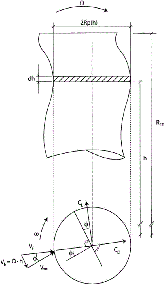
[0025] However, this important contribution has never been taken into account in the machines proposed so far employing the Magnus effect, and as a result these machines are not optimally able to exploit the Magnus effect, i.e., from a different point of view , the research and design of these machines, especially with reference to the shape of the rotating body, has not been optimized with respect to the contribution of the Earth's rotation

Method used


Image

  • Rotating blade bodies for turbines using magnus effect with rotation axis of turbine at right angle to direction of fluid
  • Rotating blade bodies for turbines using magnus effect with rotation axis of turbine at right angle to direction of fluid
  • Rotating blade bodies for turbines using magnus effect with rotation axis of turbine at right angle to direction of fluid

Examples


Embodiment Construction

[0053] It is known that the kinetic energy per unit time of ordinary flow conduits can be converted into mechanical work, and this mechanical work can be converted into electrical energy.

[0054] Recent theoretical and experimental (Badr, H.M., Coutanceau, M., Dennis, S.C.R. and Menard, C., "Crossing a Reynolds number of 10 3 and 10 4 (Unsteady flow past a rotating circular cylinder at Reynolds numbers 103and 104)", J.Fluid Mech.(1990), vol.220,459-484.; M.H.Chou, "From submerged in a uniform flow field Numerical study of vortex shedding from a rotating cylinder immersed in a uniform flow field"Int.J.Numer.Meth.Fluids(2000),vol.32,545-567; Y.T.Chew ,M.Cheng,S.C.Luo: "A numerical study of flow past a rotating circular cylinder using a hybrid vortex scheme"J.Fluid Mech.(1995) , vol.299, pp.35-71; W.M.Swonson "The Magnus effect: A summary of investigation to date (The Magnus effect: A summary of investigation to date)", Trans.ASME, D, (1961), vol. 83.No.3, P.461-470; N.M.Bych...


PUM


Abstract

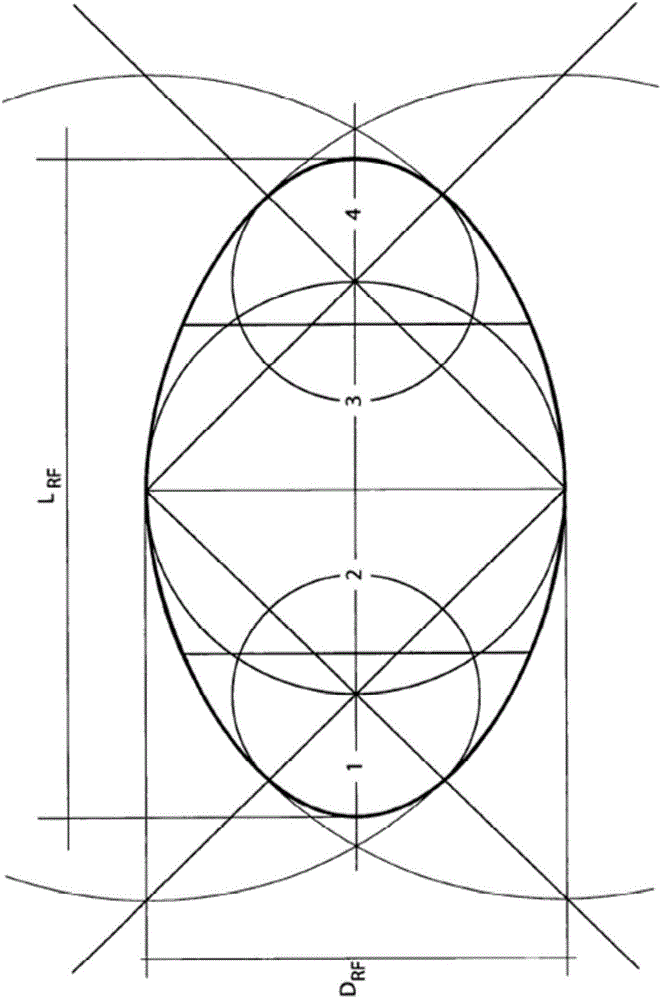
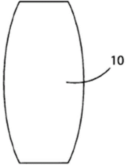
The present invention relates to a rotating body (10) for turbines using the Magnus effect with an axis of rotation of the turbine parallel to the direction of the working fluid, wherein it is obtained by an ovoid of construction of Rankine-Fuhrman, arranged with major axis (L RL ) parallel to the axis of rotation of the rotating body (10), said major axis (L RL ) of the ovoid being equal to 10 times the minor axis (D RL ), of the same ovoid, the diameter (D) of said rotating body (10) being variable along the axis of rotation of said rotating body (10) up to a maximum value comprised between 1/5 and 1/6 of the length (L) of said rotating body (10), said ovoid of construction of Rankine-Fuhrmann being divided into four sectors obtained dividing the major axis (L RF ) of the same ovoid into four segments (1, 2, 3, 4) having the same length, the profile of said rotating body being realised, respectively - following the profile of the second and third sectors into which the ovoid of construction of Rankine-Fuhrmann was divided, i.e. the sectors of the ovoid of Rankine-Fuhrmann corresponding to the second (2) and third (3) segments into which the major axis (L RF ) of the ovoid was divided, - following the profile obtained through the combined transposition of the third sector to the second sector into which the ovoid of construction of Rankine-Fuhrmann was divided, so to form two opposing trapezoids, welded along the minor base, or - following the profile obtained through the combined transposition of the fourth sector, i.e. the sector of the ovoid of construction corresponding to the fourth segment (4) into which the major axis (L RF ) of the ovoid was divided, to the first sector, i.e. the sector of the ovoid of construction corresponding to the first segment (1) into which said major axis (L RF ) of the ovoid was divided, so to form an hourglass, wherein the two sectors are connected, at the respective points of maximum curvature, by means of sections of prolated spheroid, i.e. with surfaces of quadrics of rotation with one flap.

Description

technical field [0001] The present invention relates to a rotating blade body for a turbomachine utilizing the Magnus effect, the axis of rotation of which is at right angles to the direction of a working fluid. [0002] More specifically, the invention concerns the definition of construction techniques for rotating bodies installed in hydraulic radial turbines operating according to a dynamic effect known as the Magnus effect and excited with respect to their Rotational movement of the longitudinal axis. Background technique [0003] In this context, the expression radial turbine refers to a turbine whose axis of rotation is at right angles to the direction of the working fluid. [0004] As is well known, there is a correlation between the rotation of a rotating cylinder with respect to its longitudinal axis and the flow of fluid impinging on said cylinder in a direction perpendicular to said longitudinal axis. This correlation was first described by Magnus in 1852, for w...

Claims


Application Information

Patent Timeline
Patent Type & Authority Applications(China)
IPC IPC(8): F03D1/06F03D3/00F03D3/06
CPCF03D3/007Y02E10/721F05B2240/201Y02E10/74F03D3/061Y02E10/72
Inventor A·拉焦亚
Owner E R ENERGIE RINNOVABILI
Why Eureka
Try Eureka