
Design method for cooker support of cooker used for manufacturing fried bread sticks

A design method and pot support technology, which is applied in oil/fat baking, special product baking, baking, etc., can solve the problems of increased labor costs, low yield of round pots, etc., and achieve improved product appearance and appearance color Consistent, the effect of improving the pass rate

Inactive Publication Date: 2015-08-12
龚柱
View PDF20 Cites 1 Cited by
  • Summary
  • Abstract
  • Description
  • Claims
  • Application Information

AI Technical Summary

Problems solved by technology

In order to maintain the straight shape of the fried dough sticks, it is necessary to manually move the fried dough sticks at the edge to the middle of the pot to continue frying. In order to improve the yield, multiple fried dough sticks are usually processed in the pot at the same time. Since the pot is round, and The fried dough sticks are long. Therefore, the area where the straight fried dough sticks can be placed in the pot is the middle of the pot, and the straight fried dough sticks cannot be placed near the edge of the pot unless the fried dough sticks are bent, and the curved fried dough sticks are not qualified. , therefore, the yield of the round pan is not high, and it is necessary to manually maintain the position of the fried dough sticks in the pan during the production process, which increases the labor cost

Method used


Image

  • Design method for cooker support of cooker used for manufacturing fried bread sticks
  • Design method for cooker support of cooker used for manufacturing fried bread sticks
  • Design method for cooker support of cooker used for manufacturing fried bread sticks

Examples


Embodiment Construction

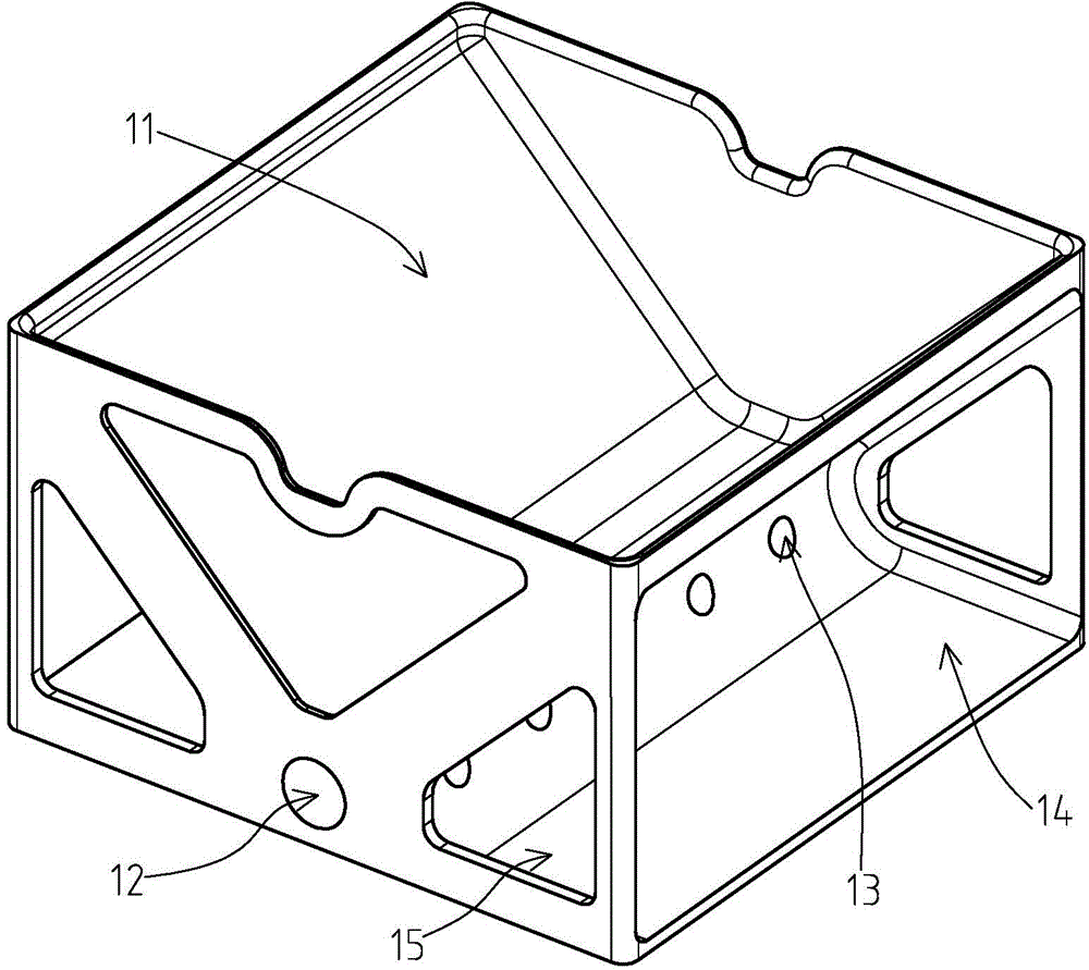
[0021] like figure 1 and image 3 As shown, it is an embodiment of a pan support for a pan for making deep-fried dough sticks disclosed in the present invention, which has a square shape, and a first receiving cavity 11 for receiving a lining is provided in the middle of the pan support. A second receiving cavity 14 for receiving the handle is respectively provided on the left and right sides of the pot support, and two special-shaped through holes for receiving the support plate are respectively provided on the front and rear facades of the pot support.

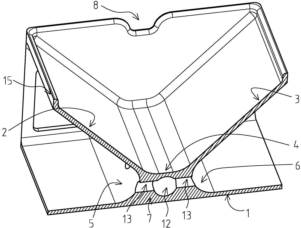
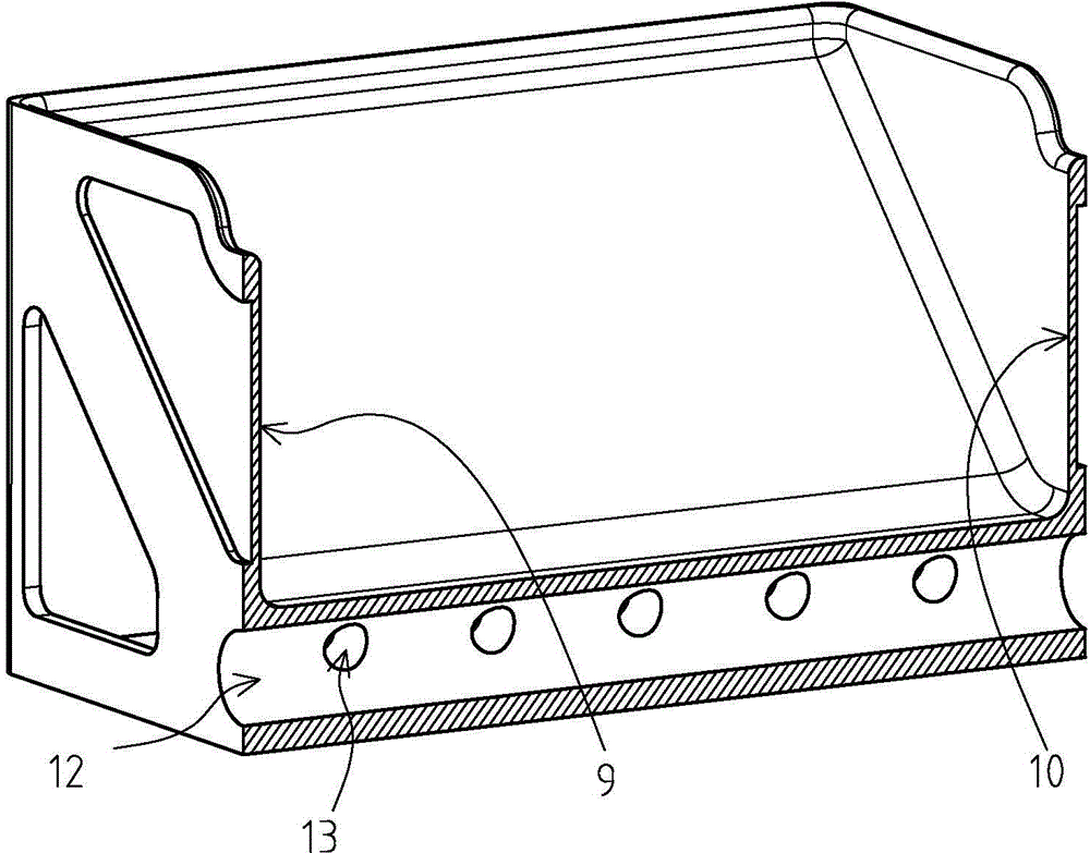
[0022] like figure 2 and image 3 As shown, it is a perspective view of the horizontal and vertical section of the pot stand. The bottom of the pot stand is provided with a first plane 1, and the middle part of the first plane 1 is provided with a protruding entity upward. The top of the entity extends to the left and right sides respectively. They are respectively the first plane 1 and the second plane 2, the first plan...


PUM


Abstract

The invention particularly relates to a design method for a cooker support of a cooker used for manufacturing fried bread sticks. The design method for the cooker support of the cooker used for manufacturing the fried bread sticks comprises a first containing cavity used for containing a lining matched with the cooker, and is characterized in that the first containing cavity is arranged to be in a shape with the wide upper portion and the narrow lower portion, a main heating area is arranged at the bottom of the first containing cavity in the longitudinal direction, and auxiliary heating areas are arranged on the two sides of the containing area; a first through hole communicated with the outside is formed in the bottom of the cooker support in the longitudinal direction, a second through hole communicated with the first through hole is formed in the bottom of the cooker support in the transverse direction, and the first through hole and the second through hole are formed in a heat collecting area at the bottom of the cooker support. The cooker support designed with the design method is used for conducting main heating and auxiliary heating, and oil in the lining further generates flow enabling the fried bread sticks to easily overturn; the through holes formed in the bottom of the cooker can be matched with a handle and a cover of the cooker to generate the chimney effect, and airflow enabling the fried bread sticks to easily overturn is further generated.

Description

technical field [0001] The invention relates to a design method of kitchen cooking utensils, in particular to a design method of a pan support for a pan utensil for making deep-fried dough sticks. Background technique [0002] The existing pots for making fried dough sticks are generally round, and the fried dough sticks floating on the oil surface will move to the edge of the pot under the action of the flow of the oil body, and finally stop at the edge of the pot. If the edge of the tool is used, the shape of the fried dough sticks will be bent into a shape similar to the edge, and the shape of the fried dough sticks will become arc-shaped, which reduces the pass rate of the fried dough sticks. In order to maintain the straight and unbending shape of the fried dough sticks, it is necessary to manually move the fried dough sticks at the edge to the middle of the pot to continue frying. In order to increase the yield, multiple fried dough sticks are usually processed at the ...

Claims


Application Information

Patent Timeline
Patent Type & Authority Applications(China)
IPC IPC(8): A21B5/08
CPCA21B5/085
Inventor 龚柱
Owner 龚柱
Learn More